CAN XL: the next step in the evolution of CAN communication
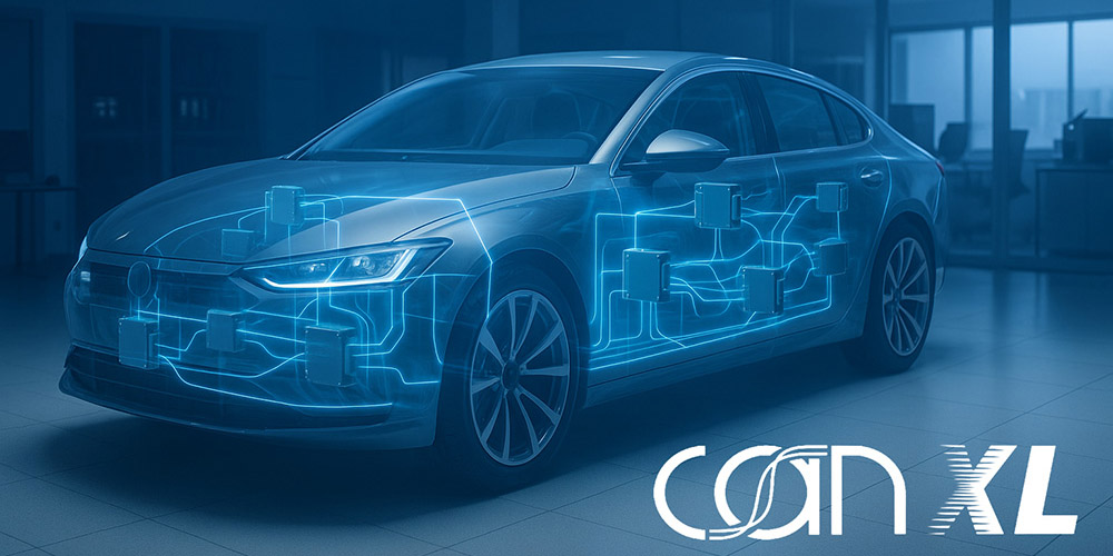
CAN XL continues the evolution of CAN — more data capacity, more throughput, and backward compatibility. Ideal for zonal architectures, sensor fusion, and a smooth migration from Classic CAN and CAN FD networks.
For more than three decades, the Controller Area Network (CAN) has been the backbone of embedded networks and industrial applications. Introduced with classic CAN, then extended with CAN FD, it is now taking a new step forward with CAN XL, which builds on the same physical principles while expanding its capabilities.
From CAN CC to CAN FD and on to CAN XL
Classic CAN, with rates up to 1 Mbit/s and eight data bytes per frame, served as the standard for years. CAN FD enabled up to 64 data bytes for the first time, with flexible bit rate switching in the data field up to 8 Mbit/s. CAN XL extends this evolution further: up to 2,048 data bytes per frame and rates up to 20 Mbit/s in switched mode. It thus bridges the gap between classic fieldbuses and modern IP-based communication architectures.
Structure and operation of CAN XL
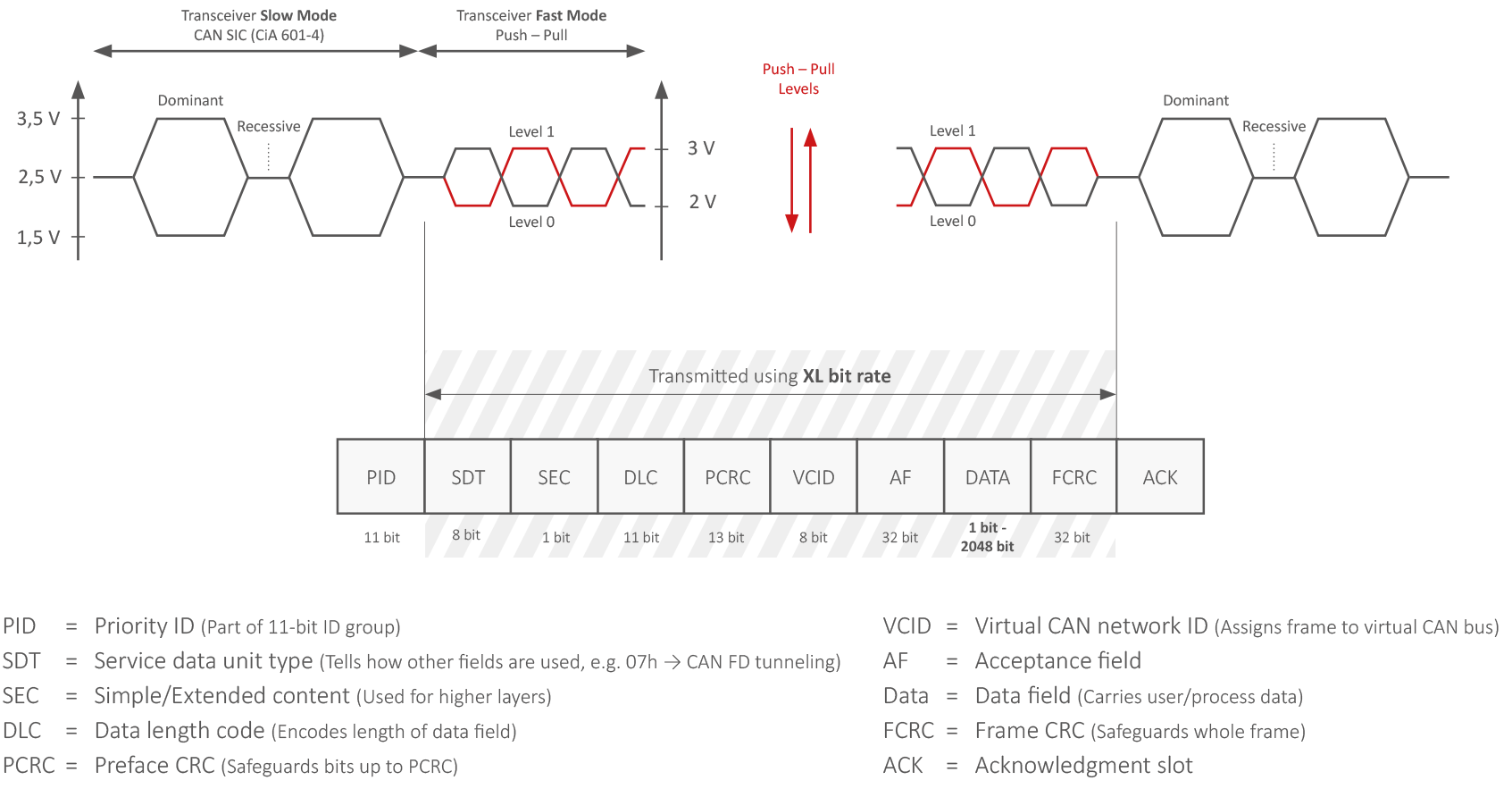
The key innovation lies in the XL frame format (XLFF), which extends the base structure (CAN ID, length, data bytes) with additional fields. The 11-bit Priority Identifier (PID) replaces the classic frame identifier for arbitration prioritization; the CAN frame identifier itself moves to a dedicated Acceptance Field. The Service Data Unit Type (SDT) defines the type of information carried (e.g., CAN FD tunneling). The SEC (Simple/Extended Content) bit indicates the use of additional headers in the data field — encryption or fragmentation. The DLC fields describe lengths up to 2,048 bytes, reducing overhead. The Virtual CAN Network ID (VCID) allows frames to be assigned to virtual networks, similar to Ethernet VLANs — a boost for zonal architectures. Finally, additional CRC fields secure the integrity of the header and the complete frame.
SIC wiring and transceivers
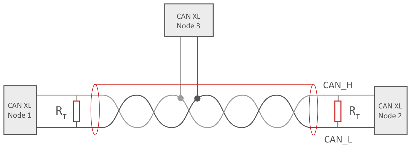
A major strength of CAN XL is its use of the existing physical infrastructure. Like classic CAN and CAN FD, it relies on a bus with CAN High and CAN Low lines, in a linear topology with two 120 Ω terminations. Migration is therefore greatly simplified, as existing wiring harnesses can often be reused. Mode switching allows switching to a specialized XL-mode transmission to reach 20 Mbit/s: the signal amplitude is reduced to one volt, with line state changes performed in push-pull. While classic error frames are limited in this fast mode, the extended CRC fields guarantee reliable communication. The switch to fast mode occurs for the data portion of the frame, as in CAN FD.
Advantages and challenges
The strengths of CAN XL lie in the combination of high data capacity and backward compatibility. With up to 2,048 bytes per frame, not only sensor data but also IP packets can be transmitted efficiently, while reusing existing CAN infrastructure (mixed Classic, FD, XL environments). Particularly valuable: the creation of virtual networks via VCID, for zonal architectures with load distribution. In return, protocol evaluation complexity increases, and above 8 Mbit/s switching mode becomes necessary, limiting traditional mechanisms such as error frames. With the CAN XL communication standard (ISO 11898-1:2024) now specified, manufacturers and suppliers can move on to practical implementation.
CAN XL or Automotive Ethernet?
CAN XL sits between traditional buses and high-speed networks. Here is how it compares to Automotive Ethernet:
| Specification | CAN XL | Automotive Ethernet |
|---|---|---|
| Max bit rate | Up to 20 Mbit/s | Up to 10 Gbit/s |
| Payload size | Up to 2,048 bytes | Up to 1,500 bytes (standard MTU) |
| Medium | Twisted pair, 120 Ω | Twisted pair, coaxial, fiber |
| Typical topology | Line with small stars | Star, tree, or ring |
| Main areas | Zonal architecture, tunneling, sensor fusion | Backbone, infotainment, high speed |
| Backward compatibility | Total with CAN Classic and CAN FD | None |
Fields of application
A key area is the implementation of zonal architectures: control units are no longer connected in a star topology to a central ECU, but communicate within functional zones and transmit their aggregated data, reducing wiring. CAN XL can also serve as a transport medium for CAN FD messages or IP data, replacing or complementing gateways. In driver assistance and sensor fusion, the large payloads allow sensor data to be efficiently consolidated toward central processing units.
The PEAK-System solution: the CAN XL Starter Bundle
PEAK-System responded early to the arrival of CAN XL with the CAN XL Starter Bundle. In addition to the PCAN-USB XL USB-CAN interface (mode switching, backward-compatible with CAN FD and CAN Classic), the bundle includes the necessary transceiver technology and the PCAN-Basic API for software integration. This makes it possible to test CAN XL in a mixed environment and gain hands-on access to analysis and development tools: the ideal starting point for exploring CAN XL in real-world projects.