100BASE-T1 and 1000BASE-T1: what engineers need to know about Automotive Ethernet
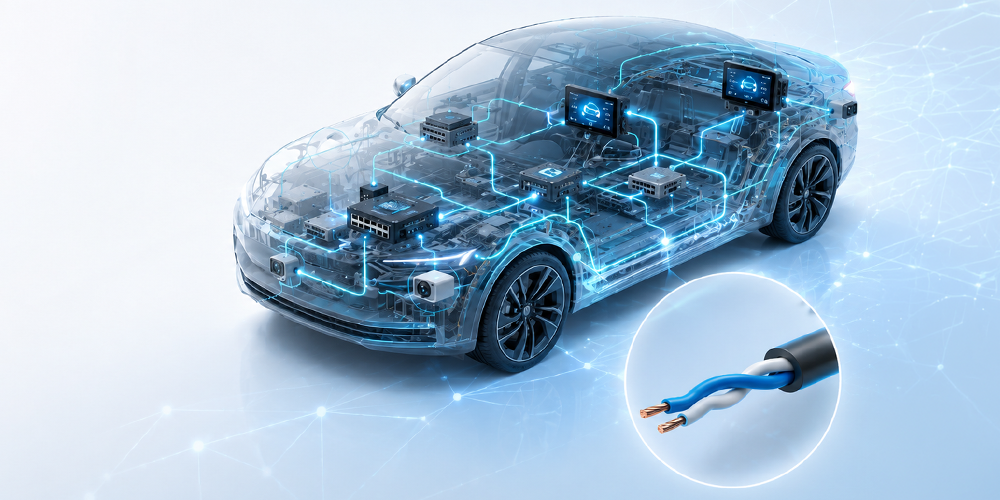
Single Pair Ethernet brings a computing-grade network into the vehicle harness, for a fraction of the cabling weight. An overview of the IEEE standards, PAM-3 signaling on the wire, and echo cancellation, which allows two PHYs to talk at the same time on the same pair.
In the era of ADAS, surround-view cameras, and zonal architectures, the data rates required in a vehicle far exceed what classic in-vehicle buses — CAN, LIN, FlexRay — can provide. But the industry's standard answer, classic Ethernet over two- or four-pair cabling, is too heavy, too bulky, and too costly for an automotive wiring harness. The solution: a family of Ethernet variants that transmit full-duplex traffic over a single twisted pair — 100BASE-T1, 1000BASE-T1, and their successors.
From office Ethernet to the vehicle harness
The single-pair adventure began outside the IEEE. In 2011, Broadcom developed a proprietary 100 Mbit/s technology, BroadR-Reach, specifically for embedded use; BMW used it as early as 2013 to connect parking assist cameras. The OPEN Alliance SIG was created to promote and standardize the approach, and the IEEE adopted it shortly after.
This results in a family of single-pair standards. 100BASE-T1 (IEEE 802.3bw, 2015) delivers 100 Mbit/s. 1000BASE-T1 (IEEE 802.3bp, 2016) applies the same full-duplex single-pair philosophy at ten times the rate. The lower end is covered by IEEE 802.3cg (2019), which defines 10BASE-T1S (short-range multidrop) and 10BASE-T1L (long-range industrial, up to 1,000 m). Higher rates fall under IEEE 802.3ch (2.5/5/10 Gbit/s) and IEEE 802.3cy (25/50 Gbit/s) for next-generation ADAS backbones.
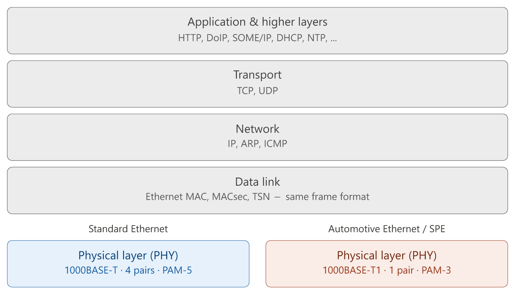
The crucial point is what these standards do not change: only the physical layer of the OSI model is new. Above the PHY, everything remains unchanged standard Ethernet — same MAC, same frame format, same EtherTypes. The same software stacks, analyzers (Wireshark), and higher-level protocols (TSN, MACsec) work without modification. To go from 1000BASE-T to 1000BASE-T1, a simple media converter that swaps the PHY is enough. This interoperability with the existing IT ecosystem is the primary reason for the rapid adoption of Single Pair Ethernet: it inherits the entire Ethernet software and tooling ecosystem for free.
SPE vs Automotive Ethernet: clarifying the terms
The two terms are often confused. Single Pair Ethernet (SPE) is strictly a physical layer family: any Ethernet variant that runs over a single twisted pair rather than two or four. The "T1" variants — 10BASE-T1S, 10BASE-T1L, 100BASE-T1, 1000BASE-T1, and multi-gigabit successors — are all SPE.
Automotive Ethernet is a broader, context-dependent term. In the strict sense, it refers to SPE PHYs meeting automotive requirements for temperature, EMC, and connectors. In common usage among OEMs and suppliers, it often refers to the entire stack running on top of these PHYs: AUTOSAR-aligned network management, SOME/IP service-oriented communication, DoIP diagnostics, security layers such as MACsec. In this sense, Automotive Ethernet is less a cable than a complete embedded network ecosystem built on IP. As an example, 10BASE-T1L is SPE but is not called Automotive Ethernet: it targets the replacement of industrial fieldbuses, with a range of several hundred meters and the option of power delivery over the same pair (PoDL).
The basis of communication: PAM-3 coding on a shared pair
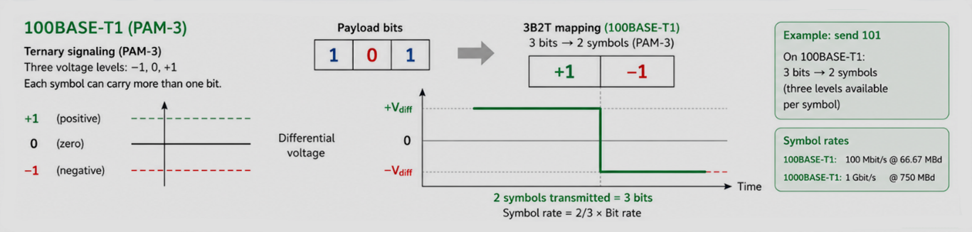
The line code for 100BASE-T1 and 1000BASE-T1 is PAM-3 — three-level amplitude modulation on the wire: −1, 0, +1. For a reader coming from CAN: CAN drives the differential pair into just one of two states (dominant/recessive), so each symbol equals one bit and bit rate and symbol rate are the same. Not so with PAM-3: each ternary symbol carries more than one bit, so the wire "beats" more slowly than the bit rate suggests — 100BASE-T1 delivers 100 Mbit/s at only 66.67 MBd, and 1000BASE-T1 delivers 1 Gbit/s at 750 MBd.
At a given data rate, 100/1000BASE-T1 therefore operates at a lower symbol rate than CAN-type binary signaling, which helps contain the fundamental frequency — and thus radiated emissions. The trade-off is paid on the receiver side: with three levels, the gap between symbols is tighter than the dominant/recessive gap in CAN, so the PHY requires adaptive equalization, precise level slicing, and echo cancellation. SPE is more tolerant of EMC limits but less tolerant of channel imperfections: noise, reflections, and impedance mismatches interfere directly. This is why 1000BASE-T1 generally requires a shielded twisted pair, whereas a CAN bus can make do with a much coarser cable.
Two transmitters, one wire: how to avoid chaos
100BASE-T1 and 1000BASE-T1 use a single pair for both directions, simultaneously. Both PHYs drive the wire at the same time, with the same signaling, without time-slicing or frequency separation. On an oscilloscope, you only see the sum: one signal, the other's signal, channel response, and reflections. From the trace alone, it is impossible to distinguish the two streams.
The trick: each PHY knows what it is transmitting. This known signal — and its expected channel response — can be modeled and then subtracted from what the PHY samples. Whatever does not match the model is, by definition, the other PHY's signal. This is the role of an adaptive digital filter, the echo canceller, complemented by an equalizer (DFE/FFE) that compensates for the cable's frequency response. Two conditions make this possible: a shared bit clock (one side master, one side slave, with the slave recovering the timing from the master's signal) and a training phase at link start-up to adjust the filter coefficients. In practice, one participant is configured as Master and the other as Slave. On PHYs that support it, auto-negotiation (IEEE 802.3 Clause 98) can automatically resolve speed and master/slave role.
Strengths and limitations
A simple unshielded twisted pair can drastically reduce connectivity cost compared to classic Ethernet, lightens the wiring harness, and complies with CISPR-25 and OEM EMC limits. And since everything above the PHY is identical to any Ethernet, the entire IT toolchain applies directly: media converters to RJ45 without protocol translation, Wireshark dissection, native diagnostics and IP service frameworks (DoIP, SOME/IP), and unmodified Linux/AUTOSAR/POSIX stacks.
The limitations are real: 100BASE-T1 and 1000BASE-T1 are strictly point-to-point; any branch, even a simple stub, requires a switch. Range is automotive-grade: about 15 m over Type A cable, with an optional Type B variant at 40 m for 1000BASE-T1. IEEE specifications impose strict channel quality limits (insertion loss, return loss, mode conversion) far more demanding than anything CAN wiring must provide. 1000BASE-T1 is significantly more sensitive to channel quality than 100BASE-T1 and generally requires a shielded pair. Finally, link startup, with its finely orchestrated master/slave protocol, makes commissioning debugging less trivial than on a CAN bus.
| Specification | 100BASE-T1 | 1000BASE-T1 |
|---|---|---|
| Standard | IEEE 802.3bw (2015) | IEEE 802.3bp (2016) |
| Bit rate | 100 Mbit/s | 1 Gbit/s |
| Online code | PAM-3, 4B3B / 3B2T coding | PAM-3, 80B/81B block coding + RS-FEC |
| Symbol rate | 66,67 MBd | 750 MBd |
| Cable and range | UTP — ≤ 15 m | Type A (UTP) ≤ 15 m ; Type B (STP) ≤ 40 m |
| Duplex / topologie | Full-duplex, point-to-point | Full-duplex, point-to-point |
| Typical applications | Cameras, infotainment, IP diagnostics | ADAS sensor links, zone backbone → ECU |
Where 100/1000BASE-T1 is used
100BASE-T1 has become the default link for cameras, infotainment connections, and diagnostics-over-IP (OBD/DoIP), replacing MOST and LVDS. 1000BASE-T1 carries higher-rate ADAS data — front cameras, lidar pre-processing, radar fusion — and serves as the zone-to-central-computer backbone in modern E/E architectures. 2.5G–10G variants are starting to appear on test benches and pilot vehicles, while 10BASE-T1S occupies the low end as a multidrop replacement for legacy CAN segments.