Fiber-optic CAN communication in an anechoic chamber
Electromagnetic compatibility testing
12 CAN networks to supervise without copper cabling
PCAN-Repeater DR, PCAN-Ethernet Gateway, PCAN-Explorer 7
The problem
A customer performing electromagnetic compatibility (EMC) tests needed to simultaneously validate several BMS (Battery Management Systems) and lithium batteries. Each BMS and each battery communicated over a dedicated CAN bus network, for a total of 12 separate CAN networks.
The operator, located outside the EMC chamber, needed to be able to monitor, analyze, and communicate with all battery packs and BMS units during testing. However, two major constraints arose:
- No copper cable: running metal cables between the inside and outside of the anechoic chamber would have skewed EMC measurements.
- Galvanic isolation: since each battery and each BMS has different electrical grounds, it was essential to avoid any ground loop between the networks.
The solution
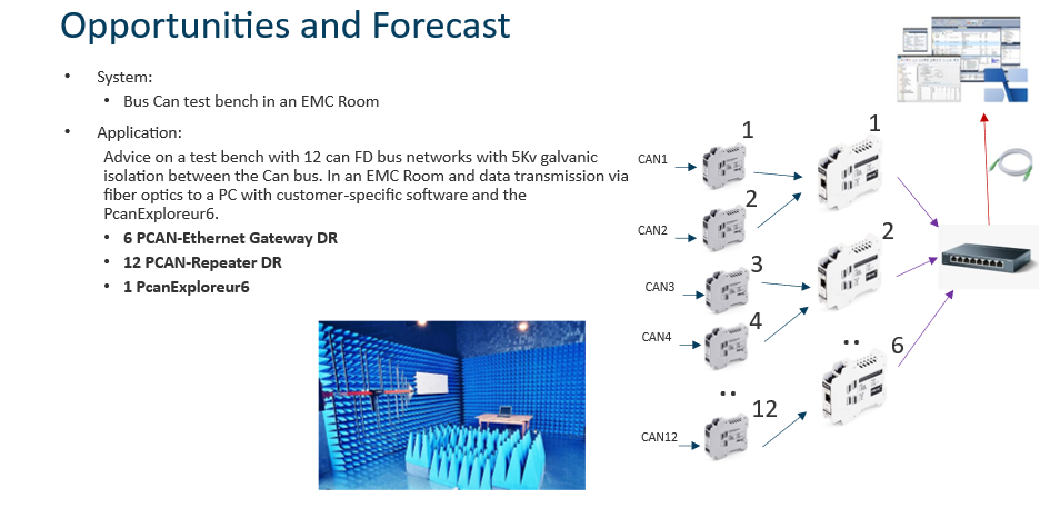
PEAK-System France has designed a three-stage architecture:
1. Galvanic isolation with the PCAN-Repeater DR
A PCAN-Repeater DR galvanic isolator was installed between each battery pack/BMS and the rest of the network. This isolation ensures that the 12 CAN networks remain fully independent from one another, with no risk of interference or ground loops.
2. CAN to Ethernet conversion with the PCAN-Ethernet Gateway
At the output of each PCAN-Repeater DR, a PCAN-Ethernet Gateway encapsulates CAN frames into IP frames. Each unit handles two separate CAN networks. For the 12 networks, only 6 PCAN-Ethernet Gateway DR units were therefore needed.
3. Fiber optic link through the EMC chamber
The 6 Ethernet enclosures are connected to a router equipped with a fiber optic link. The fiber passes through the wall of the anechoic chamber without disturbing EMC testing. Outside, a second fiber optic router is connected to the operator's PC.
On this PC, the PEAK-System virtual driver decapsulates the 12 CAN networks. The operator then uses PCAN-Explorer 7 to analyze the data in real time and, if necessary, reflash the firmware via the UDS/ISO-TP API integrated into software developed specifically for this customer.
In pictures
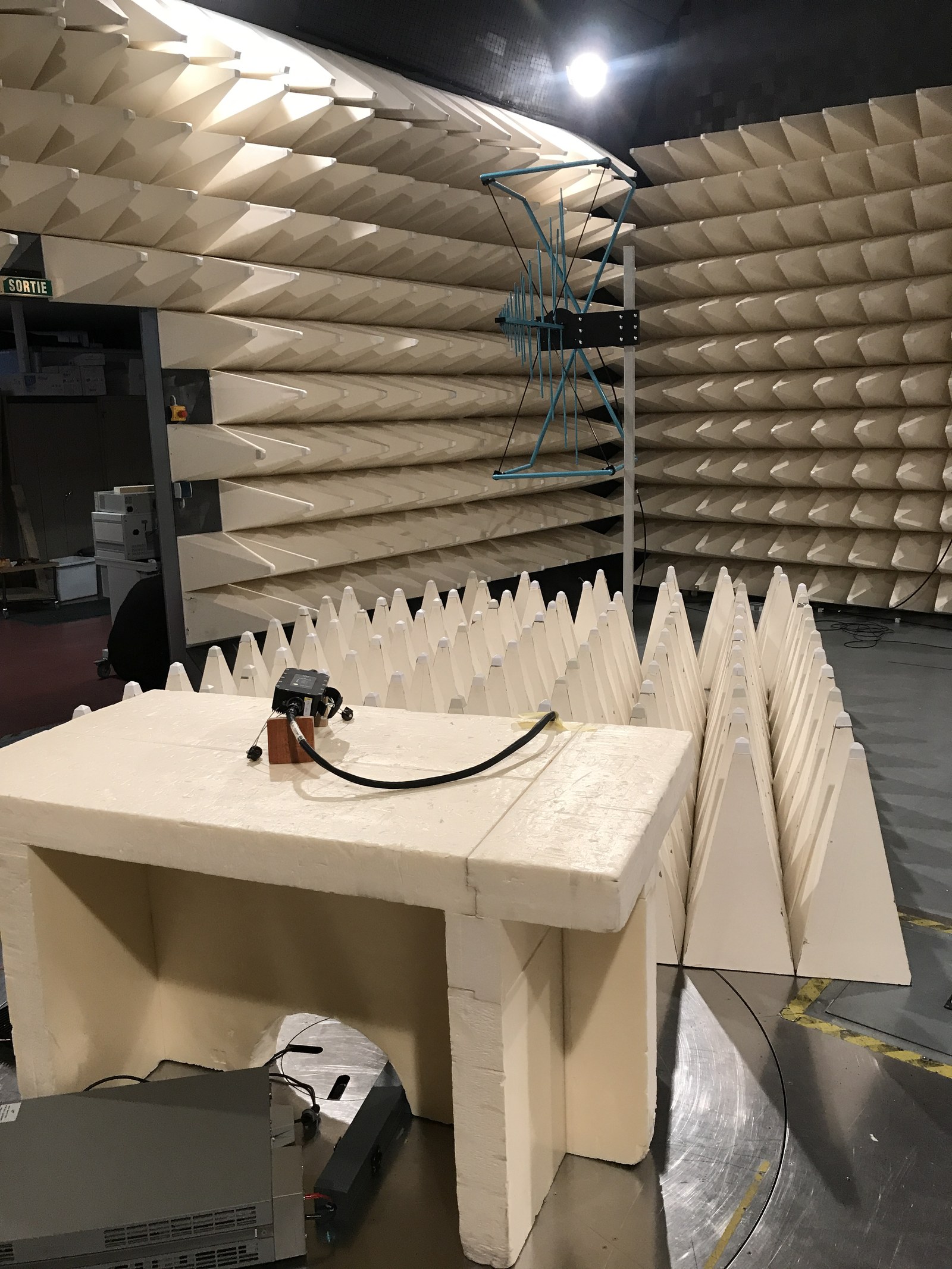
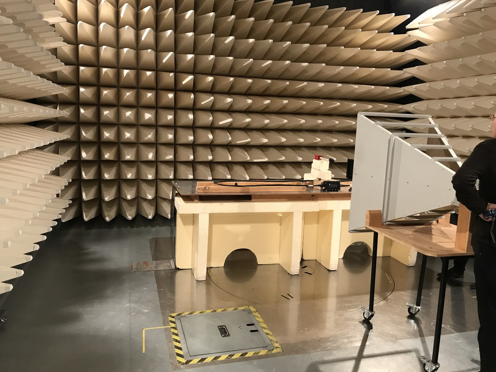
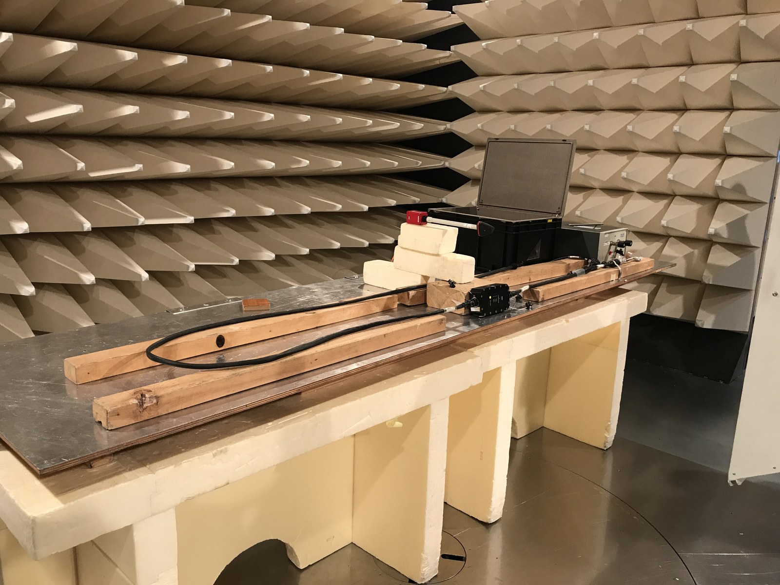
Anechoic chamber used for electromagnetic compatibility testing — Photos PEAK-System France
The result
The operator monitors and controls 12 CAN networks in real time from outside the EMC chamber, without any interference with the electromagnetic compatibility measurements. The solution is reliable, scalable, and reproducible on other test benches.