CAN (Controller Area Network)
The "history" of CAN
The availability of powerful, low-cost microelectronic components enabled the automotive industry to introduce standalone electronic control units (ECUs) for various functional domains, such as ignition, transmission control, and anti-lock systems. It quickly became clear that further functional improvements — and thus a significant improvement in driving behavior — required synchronization of all processes distributed across the various ECUs, achieved through controlled data exchange between devices.
The introduction of digital communication systems in the automotive industry was also driven by the growing number of body and comfort electronics to be connected, such as air conditioning, seat and mirror adjustment, power windows, anti-theft systems, and central locking and lighting mechanisms. In the automotive field, a digital communication system was primarily meant to reduce the amount and length of wiring, and to reduce critical wiring points, such as the passage between the cabin and the front doors.
Due to the particularly high requirements for data transmission robustness in an electromagnetically noisy environment, it was necessary to develop a suitable communication concept. This was the starting point for the development of the CAN (Controller Area Network) protocol, initiated by Bosch in 1983. Since then — in addition to use in cars — CAN has been present in a wide range of application areas:
- Utility vehicles (refuse collection and fire trucks)
- Public transport (railways, trains, trams, buses)
- Agriculture and forestry (tractors, etc.)
- Military
- Aviation and maritime
- Buildings (elevators)
- Construction (cranes, excavators, etc.)
Bus topology, number of participants
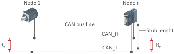
CAN networks are typically organized in linear structures with 120-ohm termination resistors at each end of the line (see figure). Stub lines are permitted to a certain extent, and a star topology is also possible (e.g. in automotive applications). The number of participants (nodes) in each network is not limited by the protocol but depends on the performance of the components used.
CAN repeaters have multiple uses when CAN networks need to be extended: they can be used to physically couple two or more segments of a CAN bus system, to implement tree or star topologies, or to add long stub lines. In addition, network segments can be electrically decoupled using a galvanically isolated repeater.
Figure 1: Linear topology of a CAN network
Messages CAN
Communication on the CAN bus takes place via "messages" that contain both control bits and data bits. The structure of such a message is called a frame.
- Data Frame: Used to transmit data from a transmitter to one or more receivers at the initiative of the data source (transmitter).
- Remote Frame: Allows a bus participant (receiver) to request the transmission of a specific message from a data source.
- Error Frame: Signals to all bus participants (transmitters or receivers) that a transmission error has been detected.
- Overload Frame: Used by a CAN controller to indicate an overload. This frame is no longer implemented today, as the performance of modern controllers is sufficient.
Message exchange based on the producer-consumer principle
Unlike node-oriented transmission, in which a message is exchanged between two specific nodes, CAN message transmission is based on the producer-consumer principle. A message transmitted by one node (producer) can be read by all other nodes (consumers). To this end, messages are not marked with a destination but with a unique message identifier. Sending messages to all nodes on a network is also called broadcasting.
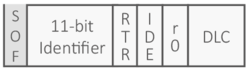
Figure 2: 11-bit identifier (standard format, CAN 2.0A specification)
- SOF : Start of Frame = un bit dominant
- RTR: Remote Transmission Request — if the RTR bit is set, it defines a Remote Frame
- IDE : Identifier Extension, 1 bit
- r0: reserved bit
- DLC: Data Length Code = 4 bits (number of bytes in the data field, 0 to 8 bytes; values 9 to 15 are not supported)
The message identifier denotes the content of the CAN message, not the device. In a measurement system, for example, a separate identifier may be assigned to temperature, voltage, and pressure parameters. However, several parameters can also be combined under a single identifier if the total data does not exceed the maximum length of the data field.
Receiving devices decide, based on the identifier, whether a message is relevant to them and filter the relevant messages from the data stream available on the bus.
The standard format of a CAN identifier is usually 11 bits, allowing 2,048 different messages per system. This number is sufficient for most applications. However, using 29-bit identifiers (extended format) allows many more different messages to be defined. Typically, the 29 bits are structured and used for special applications (e.g., trucks, SAE J1939).
Frame format
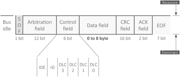
The start of a message (see image) is signaled by a leading dominant bit, followed by the 11-bit message identifier and an additional bit that distinguishes between a data message and a remote transmission request (RTR) message. A node on the network can request the transmission of a particular message from another node in the system. However, the remote node must be programmed to respond to such an RTR message.
The control field specifies the transmission format (standard/extended) of a message and the number of following data bytes.
The data field of a CAN message can contain zero to eight data bytes. The data field is followed by the 15-bit CRC segment, which allows the receiver to check the received message. In the acknowledgment field, the sender of a message waits for confirmation of error-free reception from at least one receiving node on the network. This confirmation — used exclusively for error isolation on the sender side — is provided by all error-free receiving nodes on the network by sending a dominant bit in the acknowledgment slot.
The end-of-frame (EOF) field signals the error-free completion of a CAN message transmission.
Figure 3: Format of a standard CAN message (data frame)
- Start of Frame (SOF) = a dominant bit
- Arbitration field, consisting of an identifier segment (11 bits or 29 + 2 bits) plus an RTR bit
- Control field (CTRL) = 6 bits — IDE (1 bit), reserved (1 bit), DLC (4 bits)
- Data field (DATA) = 0 to 8 × 8 bits
- Checksum (CRC) = 15 bits followed by a recessive CRC delimiter bit
- Acknowledgment field (ACK) = 2 bits (ACK bit + recessive ACK delimiter)
- End of frame (EOF) = 7 bits (recessive)
- Intermission (IFS) = 3 bits; minimum number of recessive bits separating consecutive messages
Event-driven, multi-master transmission
Each node on a CAN network can start transmitting a message as soon as the bus is free. It can happen that more than one node starts transmitting a message at the same time. A selection process (bus arbitration) is therefore needed to ensure that only one node continues transmitting its message.
Since each node can initiate a message transfer, direct information exchange between all network participants is possible. This results in a much lower bus load and a reduced need for data transmission bit rate compared to cyclic message transmission.
Lossless, bit-by-bit arbitration
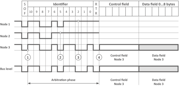
Arbitration ensures smooth and correct message transfer on the CAN bus. During the arbitration phase, it is determined which of the simultaneously transmitted messages has the highest priority. Only the node sending that message may continue transmission after arbitration. The message with the lowest identifier value has the highest priority.
During the arbitration phase, which includes transmission of the message identifier and the RTR bit, each node monitors the signal level on the bus. If a node transmitting a recessive level (a logical 1) itself detects a dominant bus level (a logical 0), it immediately interrupts its transmission process and switches to receive state. As with any bus arbitration, once a message is sent, the procedure ensures lossless bus access.
Figure 4: Principle of lossless bitwise arbitration — Nodes 1, 2 and 3 start an arbitration process at the same time. At point 2, node 2 detects that the bus does not have the recessive level it intended to transmit and cancels its process. At point 3, node 1 gives up. At point 4, node 3 transmits its data.
Priority-oriented communication
The arbitration process described above ensures that the message with the highest priority is transmitted as soon as the bus is free. The priority-oriented communication principle allows very efficient use of the available bandwidth for data transmission. It ensures that low-priority messages can use the bus without significantly delaying the transmission of high-priority messages. For the highest-priority message at a bit rate of 1 Mbit/s, the resulting maximum latency is 130 bit times.
On the other hand, when designing a CAN system, care must be taken to ensure that high-priority messages do not permanently occupy the bus. This can be achieved by introducing transmission blocking times (CANopen: Inhibit Time).
Bit rate and bus length
The bit-by-bit arbitration principle used in CAN requires a comparison of the local bit levels of all nodes distributed across the bus network within a single bit time slot. Since the signal propagation time — needed for the signal to spread across the bus — is proportional to the bus length, the duration of a bit slot must increase with bus length.
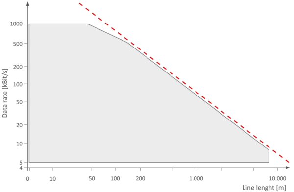
The maximum possible network size is thus essentially determined by the signal propagation time of the bus medium: at 1 Mbit/s, for example, a network range of up to 40 m is possible, while at 80 kbit/s the network size can exceed 1,000 m.
Figure 5: Relationship between data rate and cable length — The dotted line shows the rule of thumb for rates < 400 kbit/s and lengths > 100 m. The gray area shows permitted use without taking electrical transit times into account.
The maximum bus length and the maximum bit rate behave inversely. For a bus length greater than 100 m, the following rule of thumb can be used: Bit rate (in Mbit/s) × bus length (in m) ≤ 60
Error detection and fault isolation
One of the main features of the CAN protocol is its strong ability to detect transmission errors. This allows CAN to meet the very high requirements needed for networking control devices in vehicles.
The high error-detection capability is achieved by combining several measures. One of the most effective is bus-level monitoring by the sender of a message (bit monitoring). This detects all globally effective errors. In addition, each message receiver also checks every received message using the CRC segment as well as fixed-format elements. This makes it possible to detect even locally effective errors.
In addition to detecting transmission errors, the CAN protocol also includes a mechanism for identifying and disconnecting faulty nodes. This ensures that failing network nodes do not continuously interfere with message transfer.
Error signaling
Unlike subscriber-oriented transmission communication concepts, CAN — as a message-oriented protocol — follows the principle of error signaling, whereby each node checks the correctness of every message transmitted on the bus.
As soon as a transmitting or receiving node detects an error, it signals this to all other nodes by sending an error message (Error Frame). This frame contains a sequence of bits (normally invalid) of six bits of the same polarity, usually a sequence of dominant bits. All nodes detect the error signal and discard the part of the message already received. This ensures a consistent data set for all subscribers on the network.
Once a transmitting node has sent or received an error frame, it immediately attempts to retransmit the previous message via bus arbitration.
The error signaling mechanism ensures that message exchange remains accurate and consistent among all operational network participants. Since error signaling occurs immediately after error detection, very short recovery times are guaranteed. Moreover, the fact that the bus is only additionally occupied when an error occurs offers a significant advantage over acknowledgment-based methods: much lower additional bus load.
Higher-layer protocols
The CAN protocol described above, standardized in ISO 11898, corresponds to a layer 1/2 protocol in the OSI data communication model. However, additional functions are needed to build complete networks.
Two standards are widely used in embedded systems and industrial automation: CANopen and DeviceNet. CANopen is the dominant standard for embedded network applications, while DeviceNet is mainly used in industrial automation, particularly in Rockwell Automation systems. In the commercial vehicle sector, the SAE J1939 standard is also applied.
A project? A question?
Discover our catalog or contact our engineering department for tailored support.
View the catalog Contact us