Real-time CAN FD communication for e-drive and inverter test benches
ATESTEO — drivetrain testing (Germany)
Many buses, cycle rates of up to 1 kHz, a clean separation of systems
Four-channel PCAN-PCI Express FD
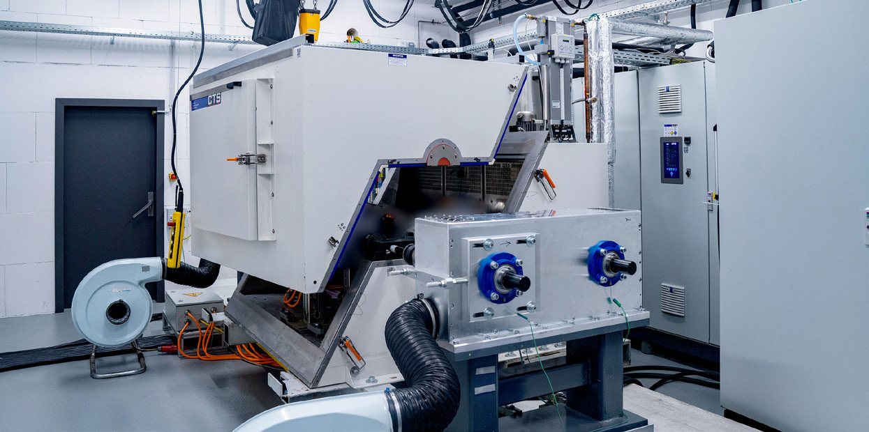
ATESTEO, one of Germany's leading drivetrain testing specialists, operates test benches dedicated to the development and validation of modern drive systems: electric motors, inverters, and their control units. Its teams rely on an in-house automation system, PDES, which controls the test programs, integrates measurement equipment and actuators, and communicates with the devices under test under realistic conditions. Real-time execution under Windows is based on the Kithara RealTime Suite, and CAN FD communication between the test PC and the ECU under test runs through the four-channel PCAN-PCI Express FD card. This case study describes a concrete example: six inverters tested simultaneously in a climate chamber.
The problem
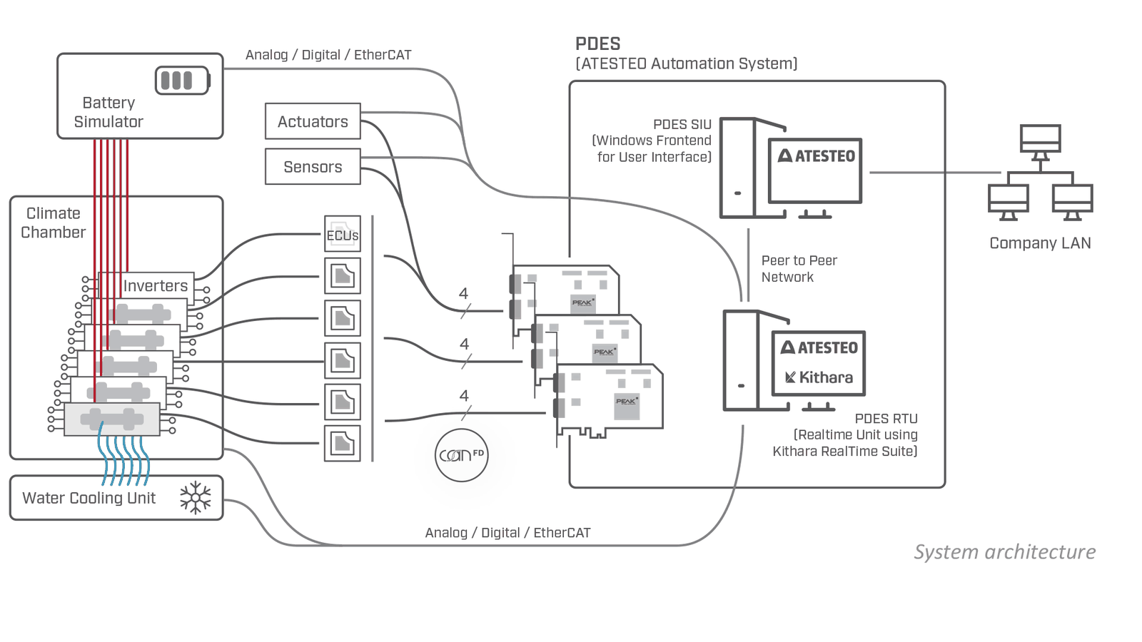
Each inverter is connected to the automation system via CAN FD. Measurement, diagnostic, and calibration data is exchanged in parallel with the ECUs via XCP on CAN FD. Depending on the test, other participants are added — battery simulators, conditioning units, sensors, actuators, water cooling — via CAN, EtherCAT, or analog and digital I/O.
A modern test bench does not test isolated components. Inverters and ECUs expect a realistic vehicle environment: they require cyclic CAN FD messages, respond to simulated operating states (residual bus simulation), and at the same time deliver their measurement and diagnostic data. Real-time communication must therefore sustain rates of 100 Hz, and often 1 kHz, i.e., processing cycles of 10 ms and 1 ms.
The solution
1. Two computers, two roles
To sustain these rates, ATESTEO splits PDES across two machines. The PDES SIU is the Windows workstation used for operation, visualization, and configuration. The PDES RTU is the isolated real-time unit that executes the test programs: it uses the Kithara RealTime Suite to run the real-time routines under Windows, exchange data via EtherCAT, and communicate via CAN FD through the PEAK cards. User interactions, remote access, and unwanted Windows processes are thus kept away from the real-time unit. The two machines communicate over a peer-to-peer network; only the SIU can be connected to the corporate network.
“We have relied on PEAK’s CAN solutions for decades, and they have continuously proven their worth in our test benches. The PEAK hardware impresses with its reliability, stable performance, and easy integration into our test bench systems. With the latest CAN XL solutions, we are already well positioned for the next era of test bench automation.”
2. The PCAN-PCI Express FD card, the central interface of the real-time unit
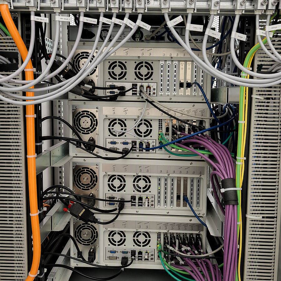
The six inverters are placed in the climate chamber. The CAN FD lines run from the automation cabinet and connect the real-time unit to the inverters' control units. On a typical test bench, ATESTEO installs up to four four-channel cards, i.e., up to 16 CAN nodes. For the setup described here, three groups of four CAN FD nodes handle the cyclic messages, the residual bus and environment simulation, and the XCP exchanges.
3. Three decisive features
- High-performance CAN FD communication, with up to 64 data bytes per frame;
- Support for CAN FD and CAN CC: older and newer ECU generations coexist in the same architecture;
- Galvanic isolation between the PC and the CAN bus, which ensures robustness amid the power electronics, inverters, and peripherals of the test bench.
PEAK hardware is also an important building block for Kithara: the RealTime Suite needs a reliable low-level connection to the CAN interface in order to integrate real-time communication directly into the automation environment under Windows.
4. Tomorrow: CAN XL already on the starting line
The test bench shows what CAN FD already makes possible in productive operation today. The requirements of upcoming ECU generations are increasing, however: higher data rates, larger payloads, more powerful communication structures. PEAK, Kithara, and ATESTEO are therefore already working on the integration of CAN XL: ATESTEO plans to integrate it into PDES, the Kithara RealTime Suite is opening up to CAN XL and CAN FD Light, and PEAK provides the hardware, the low-level documentation, and the interface technology.
“CAN XL is the logical next step for us in automotive real-time communication. That’s why we are integrating the standard into Kithara RealTime Suite at an early stage, working together with PEAK and ATESTEO to shape the technological foundation for the next generation of test bench and control unit systems.”
The result
ATESTEO tests six inverters in parallel with deterministic communication: cyclic CAN FD messages and XCP exchanges sustain rates of up to 1 kHz. Four CAN FD channels per PCI Express card provide compact, scalable multi-bus connectivity, galvanic isolation ensures safe operation in an electrically demanding environment, and the same architecture accommodates existing ECUs as well as new generations.

