Single Pair Ethernet and connected off-highway vehicles: from fields to worksites
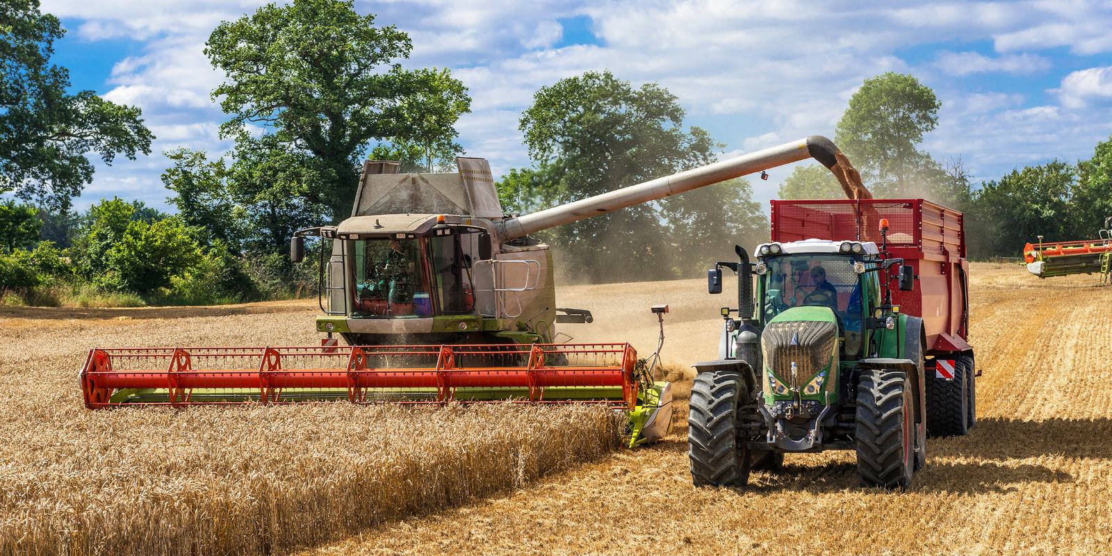
Cameras, LiDAR, and telematics are making data volumes on tractors and excavators explode. Single Pair Ethernet, proven in the automotive industry, takes on these data flows while CAN continues to handle critical control. A summary of a white paper from HMS Networks.
This white paper is intended for engineering managers and system architects in agriculture, construction, and adjacent industries. It is not a technology manifesto: it does not argue for the immediate replacement of existing protocols. Its argument is more nuanced and, in practice, more useful: Single Pair Ethernet (SPE) and the networks already running in today's machines are not rivals. They will coexist for the long term in the same architecture, each doing what it does best.
The machine has outgrown its own nervous system
A modern combine harvester films continuously with its stereo cameras to analyze crop density and detect obstacles. A single 1080p camera at 30 frames per second generates several hundred Mbit/s of raw data. Add a rear view, two side cameras, a LiDAR (tens to hundreds of Mbit/s), GNSS and inertial guidance, soil and yield sensors, and then the telematics gateway, which sends engine load, hydraulic pressures, fault codes, and yield maps to a fleet platform while waiting for over-the-air software updates.
None of these data streams is exotic: each is already in production or in trials. Taken together, according to research on fully instrumented autonomous vehicles, they approach 25 gigabytes per hour of operation. The question is therefore no longer whether the architecture needs more bandwidth, but how to get there without discarding what works.
The current architecture was not designed for this. It grew through the successive addition of nodes, segments, and gateways. The result, on many platforms, is a complex wiring harness: multiple bus segments running at different bit rates, proprietary point-to-point links for the cameras, and a growing collection of translation gateways that add latency, cost, and points of failure.
CAN remains indispensable, in a well-defined role
Introduced by Bosch in 1986, CAN now runs in billions of devices. Its strengths explain why it will remain relevant for a long time:
- Deterministic real-time control: priority is resolved at the bit level, and the highest-priority message is never delayed. For braking, engine management, or hydraulic safety functions, this guarantee is non-negotiable.
- Robustness in harsh environments: differential signaling, good EMC performance, and fault confinement that automatically isolates a faulty node.
- Simplicity: little silicon, no IP stack, no complex configuration, and a vast ecosystem of tools and trained engineers.
- Proven installed base: decades of certification and operational experience.
CAN has evolved. CAN FD raises the payload from 8 to 64 bytes and in practice reaches 2 to 5 Mbit/s in a vehicle. CAN XL, standardized in ISO 11898-2:2024, supports frames of 2,048 bytes and a theoretical data rate of 20 Mbit/s: enough for many control and diagnostic tasks, with a migration path that preserves the existing ecosystem.
Its limits stem from deliberate architectural choices. CAN is a shared bus: only one node transmits at a time, and the bus load eventually reaches saturation. Even at 20 Mbit/s, CAN XL remains two orders of magnitude below Single Pair Ethernet. Nor was CAN designed to carry IP: bridging it to an IP network works, but adds gateways. Finally, a single machine vision camera generates hundreds of times more data than a CAN network can carry, whatever the version. The task is therefore not to replace CAN, but to let it do what it does best, alongside a complementary layer capable of carrying everything else.
SPE: born in the automotive industry, proven in the field
In the early 2000s, rear-view cameras began appearing in premium vehicles. Standard Ethernet had the required bandwidth, but its physical layer — four pairs, shielded connectors — was too heavy, too expensive, and too sensitive to the vibration, temperatures, and interference found in a vehicle. The answer came from a collaboration between Broadcom and BMW: an Ethernet physical layer redesigned for automotive use, 100 Mbit/s full-duplex over a single unshielded twisted pair, standardized in 2015 as 100BASE-T1 (IEEE 802.3bw). 1000BASE-T1 followed in 2016, then the 2.5, 5, and 10 Gbit/s variants. Automotive volumes, hundreds of millions of components per year, have made SPE economically competitive.
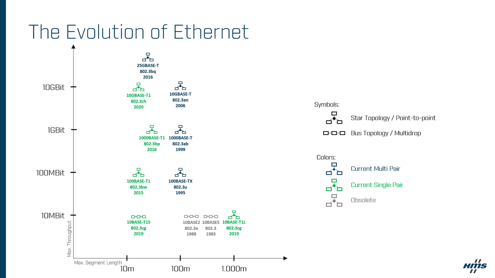
SPE is not a single standard but a family, each member of which targets one layer of the vehicle architecture:
| Variant | Bit rate | Characteristics | Use on a machine |
|---|---|---|---|
| 10BASE-T1S | 10 Mbit/s | Multidrop: up to 8 nodes on a 15 m segment, without a switch; deterministic access via PLCA | Distributed sensor arrays, cab controls, connection to the attached implement |
| 100BASE-T1 | 100 Mbit/s | Full-duplex point-to-point, 15 m on unshielded pair; the most mature variant | Camera feeds, telematics gateway, ECU-to-ECU links |
| 1000BASE-T1 | 1 Gbit/s | 15 m on unshielded pair, up to 40 m on shielded pair | Backbone to the central compute unit, sensor aggregation |
| 2.5 / 5 / 10GBASE-T1 | Multi-Gbit/s | IEEE 802.3ch, backbone of zonal architectures | Centralized computing, multi-sensor fusion, autonomous systems |
Three differences matter in practice. One pair instead of four: 1000BASE-T1 delivers the data rate of Gigabit Ethernet over a single pair, which changes what is physically possible to install. Multidrop: 10BASE-T1S brings a bus topology to Ethernet, familiar to anyone who knows CAN, with IP-native nodes. IP from sensor to cloud: everything that runs over IP runs over SPE without translation, whether over-the-air updates, telemetry, or diagnostics.
Three machines, three architectures
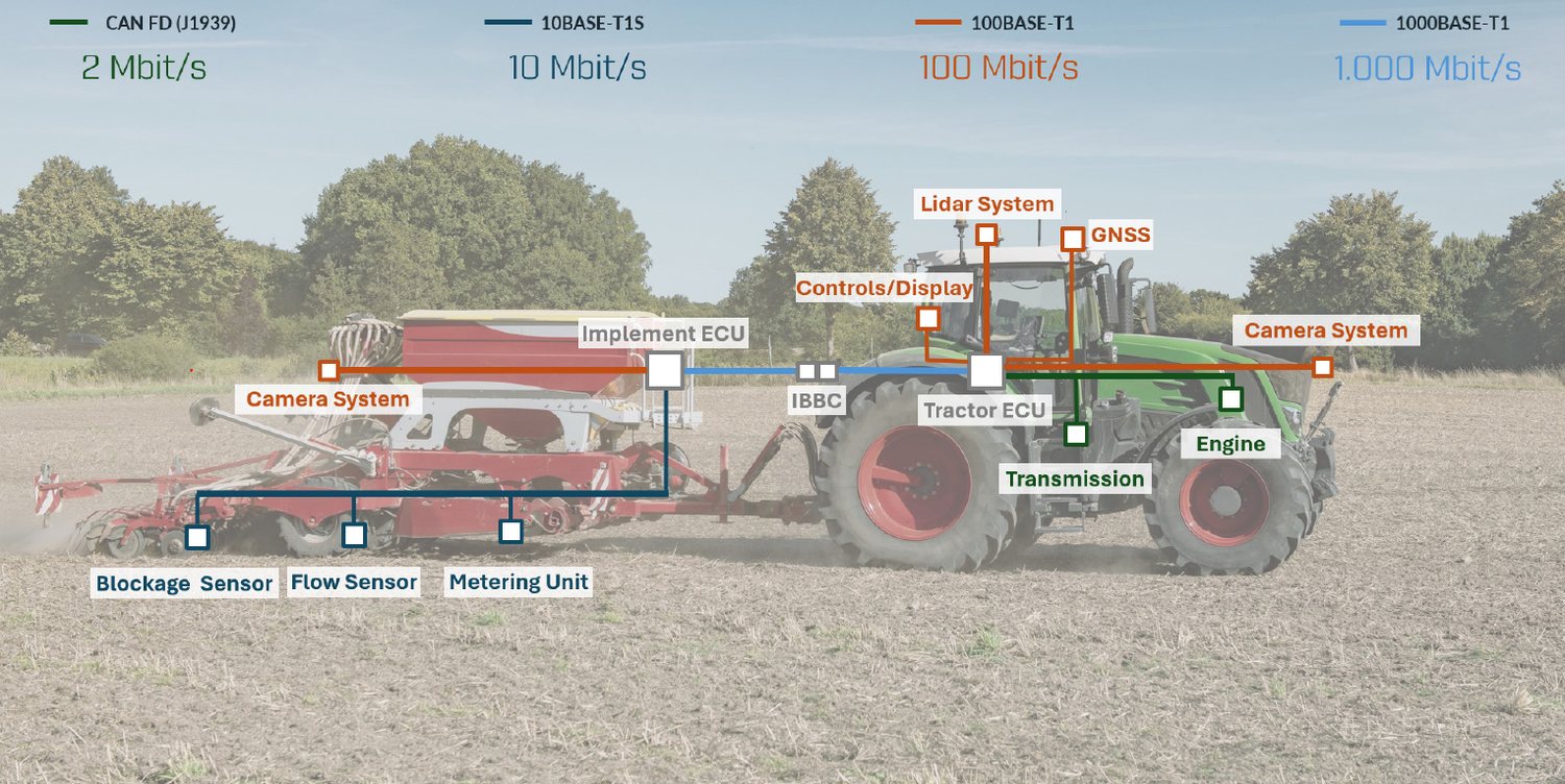
1. Agriculture: the autonomous machine
On a current precision-farming tractor, stereo cameras, LiDAR, GNSS-INS positioning, and implement sensors arrive as so many separate subsystems, each with its own proprietary cabling. The SPE architecture is not a revolution but a consolidation: a 1000BASE-T1 backbone connects the central compute unit to the cameras, the LiDAR, and the telematics gateway, using the same cables, the same switches, and the same IP addressing scheme. In the sensor zones, a 10BASE-T1S multidrop segment replaces the point-to-point wiring. The CAN network that manages the engine, the transmission, and the hydraulic safety functions, for its part, is not touched.
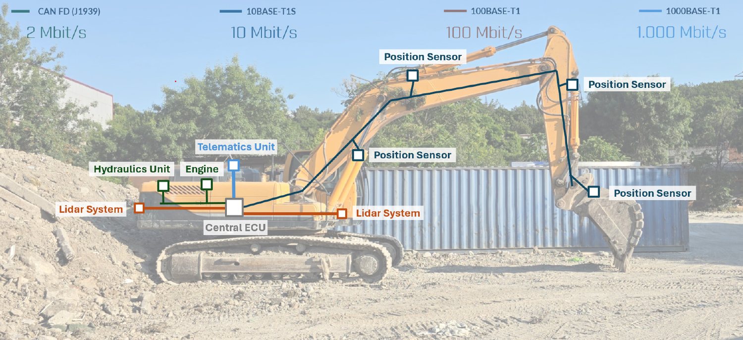
2. Construction: the connected excavator
A large crawler excavator already generates a great deal of data: hydraulic pressures and temperatures, engine load cycles, bucket position to the centimeter, cameras on all four sides. But these data streams do not come together, and most never leave the machine in a usable form. The bottleneck is not in the software; it is in the network. With an SPE backbone, the four camera feeds are consolidated onto a 1000BASE-T1 network around a central switch; the payload weighing system, the GNSS receiver, and the operator display share the same Ethernet domain. The telematics gateway, a rugged Linux computer mounted on the machine, processes, compresses, and transmits to the cloud over LTE, and receives updates over the same path. Here again, CAN and CAN FD control is fully retained: the transition is additive.
3. Drones: every gram counts
On a drone, every gram of wiring harness is one gram less of battery, payload, or flight time. Replacing four-pair camera cables with single-pair 1000BASE-T1 links directly reduces the cross-section and mass of the cabling, and moving from a mix of proprietary interfaces to a single Ethernet network reduces the number of connectors. The flight controller, the motor speed controllers, and the battery management system remain on CAN or CAN FD, leaving the certified architecture untouched.
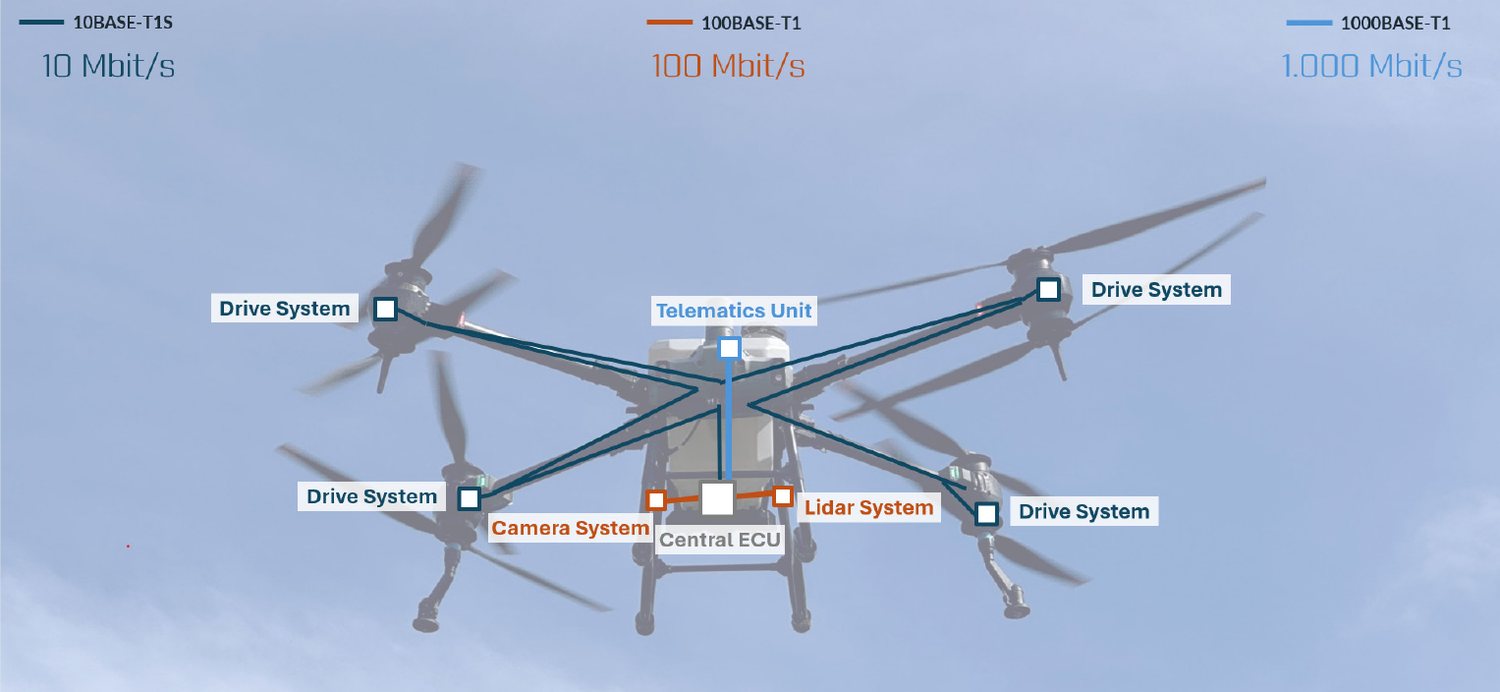
Set side by side, the three scenarios reveal the same architecture. SPE carries the high-bandwidth, IP-native data flows — cameras, sensors, telematics, compute — over a unified, lightweight backbone. The existing control network keeps what it was designed for. And a gateway layer bridges the two worlds during the years it will take for the installed base to evolve. This is not a compromise: it is a division of labor.
Where to start
Before choosing a variant, four questions frame what follows: where is the bandwidth ceiling of the current architecture? Which subsystems lack IP connectivity? Where are the pain points in the wiring harness? What is the horizon: new platform, next generation, or retrofit?
Contrary to a common misconception, the tooling is mature: because SPE has entered volume production in the automotive industry, protocol analyzers, diagnostic tools, and CAN-to-Ethernet gateways are available from established suppliers. For a team with no SPE experience, the white paper proposes a five-step path:
- Audit and map the current network, and identify the three or four data flows that are already saturating the network or will do so in the next generation.
- Prototype one link, typically a camera feed or the telematics gateway connection, on the bench, using 100BASE-T1 or 1000BASE-T1, alongside the existing CAN bus.
- Evaluate the CAN boundary: the gateway between the control network and the SPE backbone is the most sensitive element of the hybrid architecture.
- Run a field trial on a single machine, under real conditions of vibration, temperature, and electromagnetic environment.
- Scale the architecture step by step, adding sensor zones and migrating further subsystems, while CAN remains in place.
The tools to get started
To evaluate SPE alongside a CAN architecture, you first need visibility into both networks at once. The PAE-Media Converter converts the 100BASE-T1 and 1000BASE-T1 physical layers to standard Ethernet: SPE traffic becomes accessible to the usual analysis tools. The Ixxat Mobilizer Pro 820 goes further: this standalone test and development gateway combines eight CAN FD interfaces and two 100/1000BASE-T1 Automotive Ethernet ports to log CAN and SPE simultaneously, simulate the ECUs missing from the test bench, and flash firmware over the network. On the machine side, the Owasys owa5X, a quad-core Linux computer with IP67 and IP6K9K protection, is the kind of embedded compute node placed at the heart of these architectures: it aggregates sensor data, processes it locally, and manages the secure connection to the cloud, linking CAN buses and Ethernet interfaces in a single ruggedized housing.
The wire, in the end, is the simplest part: a twisted pair, lighter and thinner than what it replaces, carrying more data than the neighboring networks were ever designed to carry. SPE is not a revolution imposed on off-highway vehicles from outside, but the foundation their own ambitions were calling for, arriving proven from the roads to the fields.
Further reading: 10BASE-T1S explained and our Automotive Ethernet overview.

