Five ways to extend CAN and CAN FD range on an automotive test bench
How can CAN FD signals be transmitted reliably over long distances? Five proven architectures, all based on Ethernet, keep a test bench stable, low-latency, and free from interference.
From end-of-line testing to complex system tests, engineers often have to bridge significant distances between ECUs, measurement gantries, and measurement equipment. In many cases this was feasible with a CAN CC network. CAN FD brings higher data rates, but its faster clocking significantly reduces the permissible line length. Without appropriate technical measures, the result is communication dropouts, erroneous messages, and an unstable system.
The initial problem
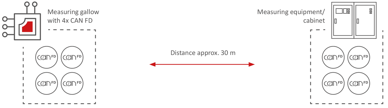
On an automotive test bench, the ECUs are connected to the automation system and the measurement equipment via a measurement gantry. In the scenario considered here, this gantry has four CAN FD channels, most often operated with an arbitration bit rate of at least 500 kbit/s and a data bit rate of 2,000 kbit/s; some applications go up to 1,000 kbit/s for arbitration and up to 5,000 kbit/s for data. The distance between the gantry and the measurement equipment cabinet often exceeds 10 meters, in an environment subject to electromagnetic interference from inverters, electric motors, or variable frequency drives.
Without countermeasures, these distances distort and attenuate the signal or cause reflections on the bus, resulting in disturbances, sporadic errors, or even system downtime. Signal quality is rarely measured, even during acceptance testing of the installation: it is therefore always advisable to measure it and record the result for later comparison.
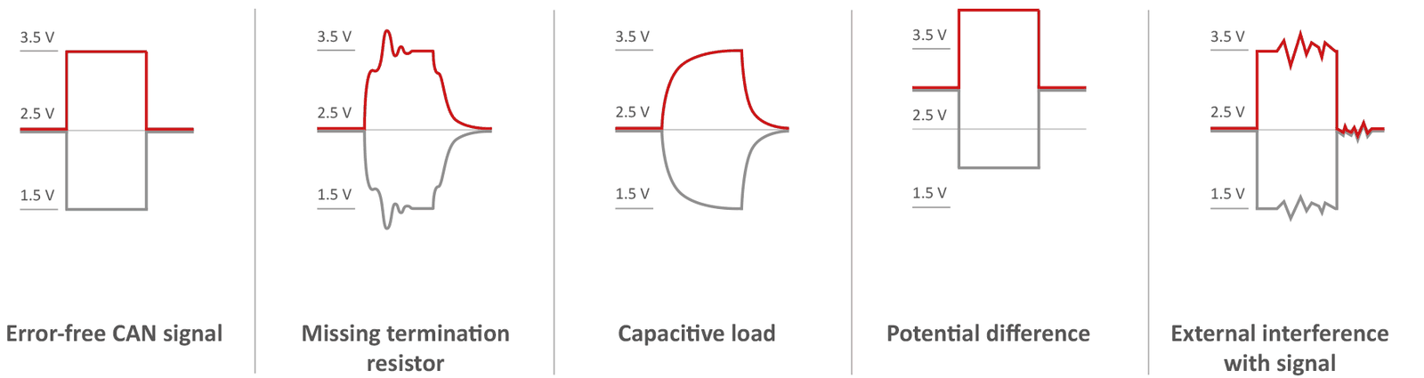
The challenge is therefore to carry these CAN FD links over the entire distance with low latency, without degrading signal quality or performance, while ensuring galvanic isolation and availability during testing.
Approach 1: two CANnector L automotive gateways
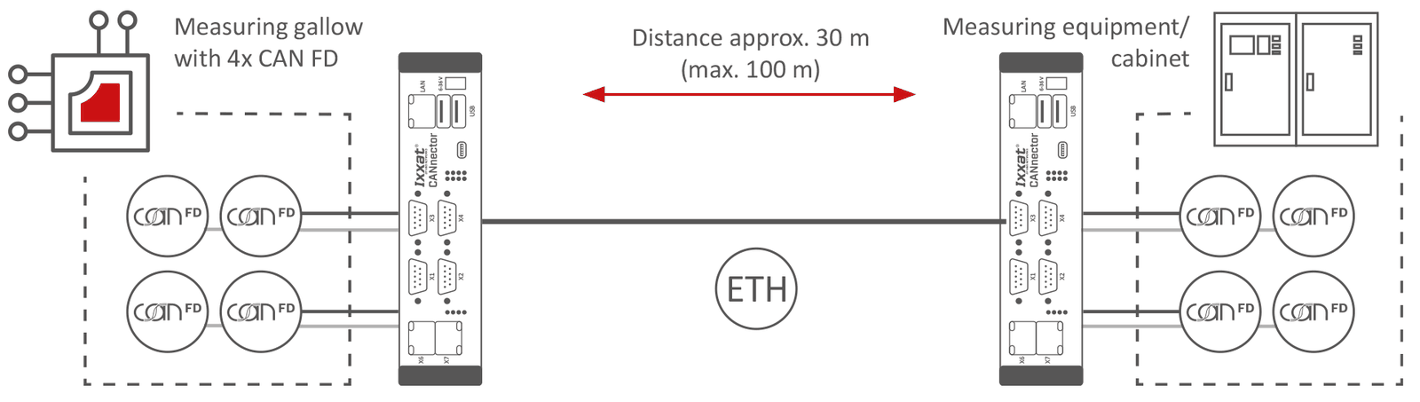
The first solution is based on the Ixxat CANnector L, a multifunctional automotive gateway that adds range extension to the usual bus connectivity. One device is placed at each end of the setup: one at the measurement gantry, the other on the automation or measurement equipment side. Mounted on a DIN rail in a cabinet, they are also suitable for mobile applications. Each CANnector L handles up to four CAN FD channels, carried from one end to the other over a low-loss Ethernet link.
Galvanic isolation on the CAN side limits interference, and data logging, residual bus simulation, and analysis functions are available as well. Users can configure filters and load DBC or ARXML files directly onto the devices; the data stream, or part of it, can be distributed to other devices, which lets calibration and diagnostic engineers connect their tools without disturbing the overall system. Relocating the residual bus simulation to the device at the gantry enables real-time simulation (including MATLAB/Simulink) right next to the ECU, independent of the automation system used.
For more computing power, up to eight CAN FD channels, or other bus systems (FlexRay, LIN, Automotive Ethernet), the Ixxat Mobilizer series can replace the CANnector.
Approach 2: four compact CAN-to-Ethernet gateways
The second solution uses the Ixxat CAN@net NT 420 or the PCAN-Ethernet Gateway FD DR, compact devices designed for Ethernet-to-CAN bridging. Two devices are installed on each side. As with the CANnector L, the data travels through an Ethernet tunnel, using TCP/IP or UDP, which ensures transparent communication between the endpoints with minimal latency. Highly cost-effective, this solution is particularly well suited to permanent installations where the number of channels is known and advanced functions are not needed.
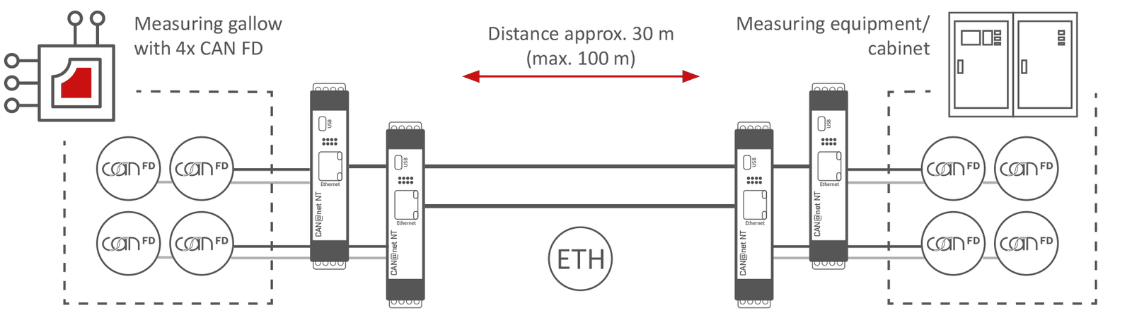
Approach 3: the hybrid architecture
The third variant combines the strengths of the first two. On the master side, a high-performance CANnector L handles the connection to the device under test and provides residual bus simulation or logging. On the other side, several CAN@net NT 420 units act as slaves: they distribute the signals via Ethernet and bridge the distance. This solution suits large test benches whose data must be distributed to several points: measurement equipment, control room, diagnostic station.
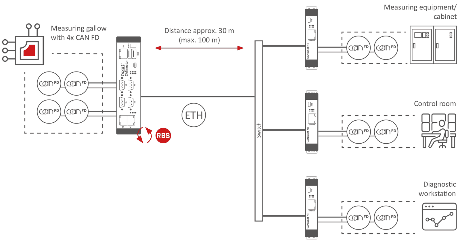
Approach 4: the distributed structure, with roles reversed
The fourth approach also combines the CANnector L and the CAN@net NT 420, but with a different allocation of roles and a different use. The data from several identical devices under test is given an ID offset by the CAN@net gateways, specific to each device. It can then travel over a single shared channel, with each message remaining unambiguously attributable. Configuration is done in ACT, a free engineering tool that also supports DBC and ARXML files.
In the cabinet, a CANnector equipped with a large number of CAN and CAN FD interfaces splits the data stream received via Ethernet and outputs the data device by device, based on the ID offset, on its CAN or CAN FD channels. Each device under test thus gets its own connection to the measurement equipment.
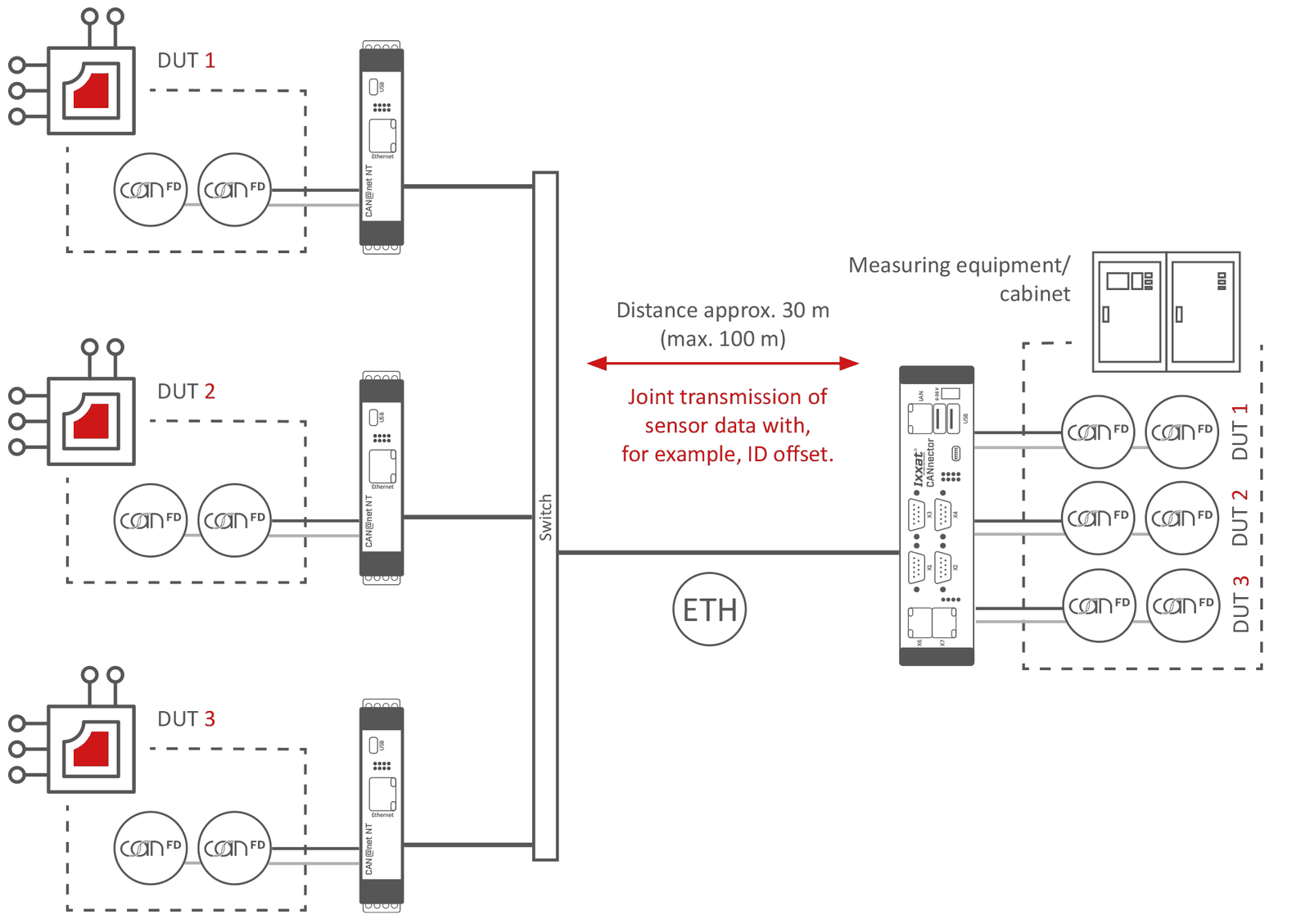
Approach 5: the low-budget UDP link
The final option is a very economical single-channel CAN FD solution: two Ixxat CAN@net Basic devices connected via UDP exchange data in both directions. On a dedicated Ethernet network, the drawbacks of UDP are generally acceptable, and its protocol overhead is significantly lower than that of TCP/IP. Latency is therefore very low: around 0.3 ms on average, with jitter below 0.2 ms, values that naturally depend on the overall system and the bus load.
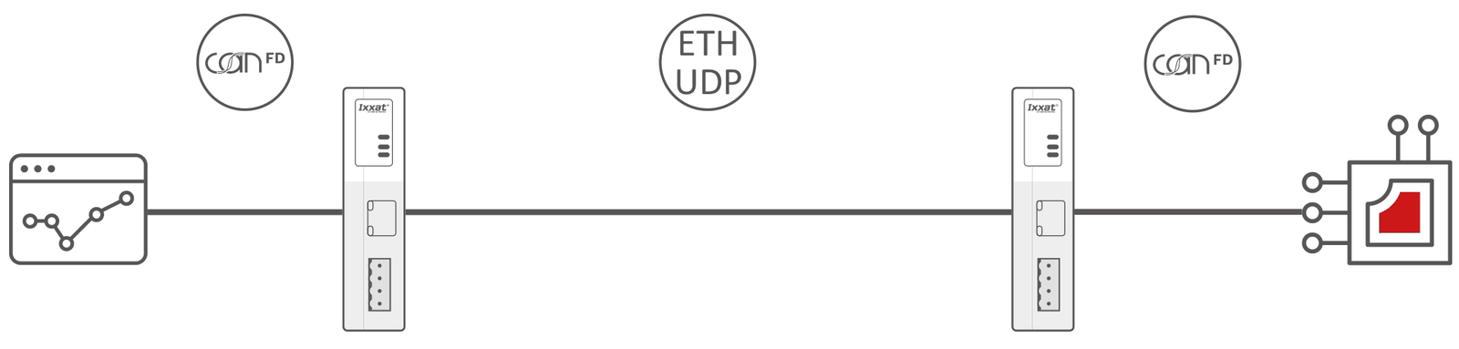
Comparison of the five solutions
| Criterion | 1. CANnector L | 2. CAN@net NT 420 | 3. Hybrid | 4. Distributed hybrid | 5. CAN@net Basic |
|---|---|---|---|---|---|
| Structure | Two identical CANnector L units, one at each end | Two CAN@net NT 420 units per side, pure gateway function | CANnector L on the DUT side, several CAN@net NT 420 units opposite: distribution to multiple points | Several CAN@net NT 420 units on the DUT side (aggregation), CANnector on the measurement side (splitting) | One CAN@net Basic per side |
| Flexibility | Very high: logging, residual bus simulation, and analysis on both sides | Low to medium: CAN frame transport only | High on the DUT side, compact on the opposite side | Compact on the DUT side, high on the opposite side | Low to medium: CAN frame transport |
| Cost | High (maximum features) | Low to medium (optimized) | Medium | Medium | Very low |
In summary
Depending on the test environment, the budget, and the functions required, there is a suitable solution for extending the range of a CAN or CAN FD bus: from the full-featured CANnector L to the compact CAN@net NT 420, by way of hybrid architectures and the low-budget UDP link. All aim for the same thing: a stable system, minimal latency, and a flexible, long-lasting test setup.

