Advanced Configuration Tool (ACT)
Configuration software for the Mobilizer, CANnector and FRC-EP series
Compare the three variants
Freeware — free of charge, covers the essentials: logging, gateway, visualization, C user code, EtherCAT.
Lite — adds Matlab/Simulink, XCP, FDX and OPC UA.
Standard — adds residual bus simulation (RBS), signal manipulation and error injection.
| Variants & functions | Standard | Lite | Freeware |
|---|---|---|---|
| Product page | View | View | Download |
| Reference | 1.12.0248.00001 | 1.12.0248.00000 | — |
| Price excl. VAT | 6,119.00 € | 2,460.00 € | Free |
| IxAdmin | ✔ | ✔ | ✔ |
| Logging (Logger) | ✔ | ✔ | ✔ |
| Gateway | ✔ | ✔ | ✔ * |
| C user code | ✔ | ✔ | ✔ |
| Visualization | ✔ | ✔ | ✔ |
| EtherCAT | ✔ | ✔ | ✔ |
| Matlab / Simulink | ✔ | ✔ | — |
| XCP | ✔ | ✔ | — |
| FDX | ✔ | ✔ | — |
| OPC UA | ✔ | ✔ | — |
| RBS, signal manipulation & error injection | ✔ | — | — |
* FlexRay receive only. Prices in EUR excluding tax.
What ACT does
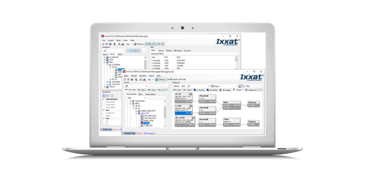
The Advanced Configuration Tool is a powerful and easy-to-use PC software package for Windows. It is used to create configurations for the Mobilizer, CANnector and FRC-EP gateways, including residual bus simulation. Once created, the configuration is downloaded to the device, which then runs it standalone.
Easy to operate
Device configuration and management via drag & drop and graphical elements.
Scalable
Three variants, extensible via C user code and Matlab/Simulink models.
Signal interpretation
Common database formats: DBC, LDF, FIBEX, ARXML, A2L.
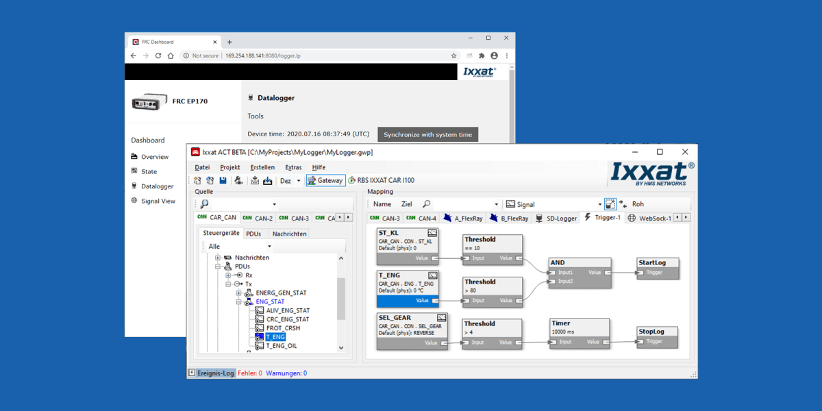
Vehicle data must be recorded so it can be evaluated offline later. The volumes involved call for intelligent data-limiting mechanisms: selective logging of individual signals or messages using filters, event-triggered start/stop, and automatic overwriting of old data that is no longer needed.
Logging also has an energy-saving standby mode, which the "Wake On" function ends immediately as soon as the product is in use.
Data can be recorded on a message basis or a signal basis, whichever suits the application best. Triggers are free-form: exceeding a threshold, receiving defined messages, or a logical combination of several events.
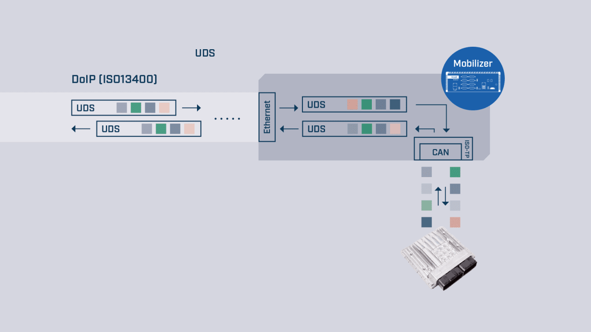
Various diagnostic protocols are supported. Diagnostic data and update functions can be sent to ECUs via the optionally available D-PDU API or via DoIP.
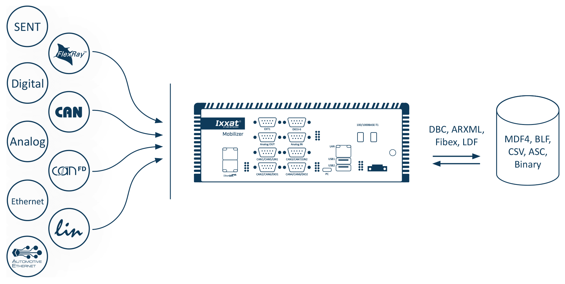
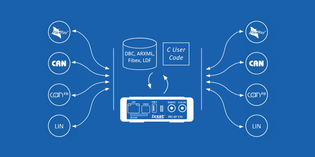
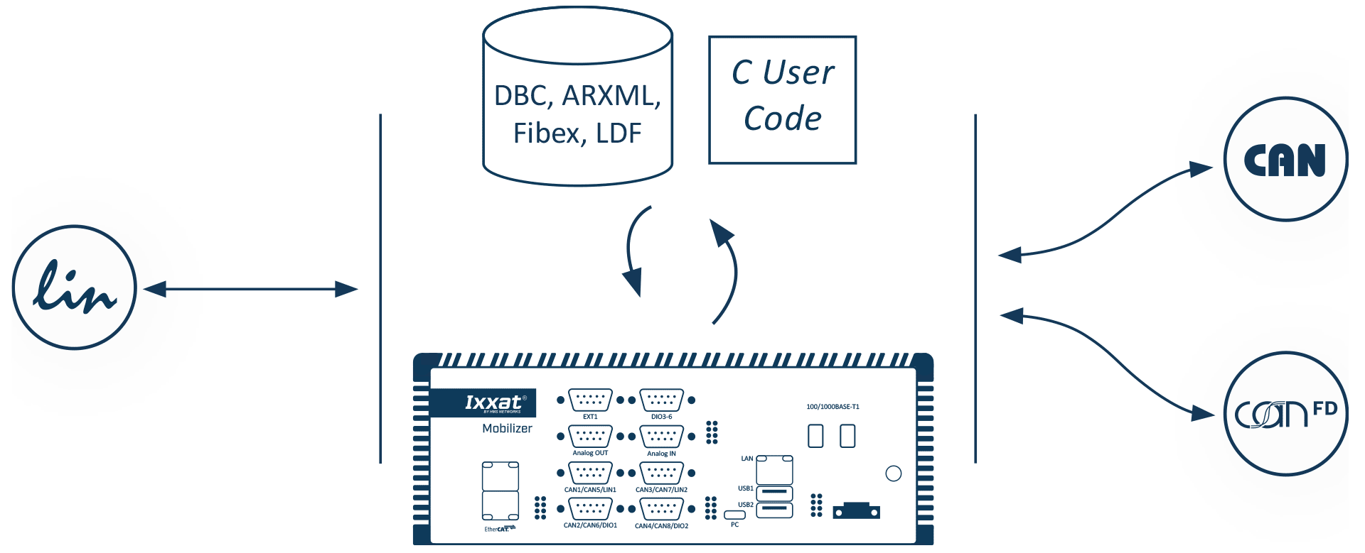
The gateway is the main application of every configuration running on a CANnector, Mobilizer or FRC-EP. It is not limited to transferring data from one CAN bus to another: it also connects logical bus systems (user code, data logger, Matlab/Simulink and so on) to the overall data exchange. Every frame, PDU or signal can therefore be routed individually from source to destination, directly or through custom code that manipulates the data on the fly.
Configuration happens in the ACT gateway view, by drag & drop: take the data from the source bus and drop it on the destination, whether that is a real bus, the user code or the logger.
FlexRay / CAN / CAN FD / LIN — bus description files can be used but are not required. When provided, they let you configure a signal-based gateway and combine signals from several source messages into a single target message. If the physical signal representation differs between source and destination, an automatic signal transformation can be enabled, or handed over to your user code or a Matlab/Simulink model for complex adjustments.
Transmission on the destination bus is configurable: event-triggered by the reception of one or more source signals, by a change of value, cyclically at the cycle time defined in the CANdB or at a manually adjusted rate, based on a trigger signal, or any combination of these. Signals that do not need to change can be given a default value, either from the bus description file or defined manually.
To connect a CAN, CAN FD, FlexRay or LIN system to modern industrial communication, simply choose a CANnector, Mobilizer or FRC-EP with the EtherCAT extension. In ACT, drag & drop generates the mappings from and to the EtherCAT slave, and the corresponding ESI file is produced automatically: it works with any capable EtherCAT master to configure the network.
Once connected to EtherCAT, all data — from the CAN, CAN FD, FlexRay or LIN bus, or from any other EtherCAT sensor or I/O device — is distributed synchronized, on the same communication system, to the PLC or PC controlling the test.
Analog and digital inputs / outputs — the I/O ports of the FRC-EP, Mobilizer and CANnector devices are used like any other signal. After configuring the data direction, range of values, conversion rules and unit, they can be mapped by drag & drop from or to any bus.
The Generic Ethernet protocol is a virtual CAN, CAN FD, FlexRay or LIN bus carried over Ethernet: it reduces cabling and bridges long distances. Data travels over Ethernet and is turned back into physical protocols by a second CANnector, Mobilizer or FRC-EP — the classic range extender. To connect the stream directly to a PC, the VCI driver lets you use the device as a remote PC interface.
Up to 16 such virtual buses can be configured, towards as many different IP addresses or ports: you build your own Ethernet-based network and keep CAN, CAN FD, FlexRay or LIN only on the last mile. The protocol also allows combining Ixxat CAN@net devices, which extends the setup to up to 136 CAN or 72 CAN FD interfaces if you run short of ports.
Virtual bus — ACT lets you add a virtual bus to the configuration to define your own environment variables, which can be mapped by drag & drop from or to any other bus. A variable calculated by your user code can therefore be reused anywhere else.
FDX and DBC generator — the Fast Data Exchange protocol is a simpler alternative to XCPonEthernet for connecting third-party software: ACT generates the XML description file to import. The gateway function can also generate DBC files from the mapping of the physical and logical buses.
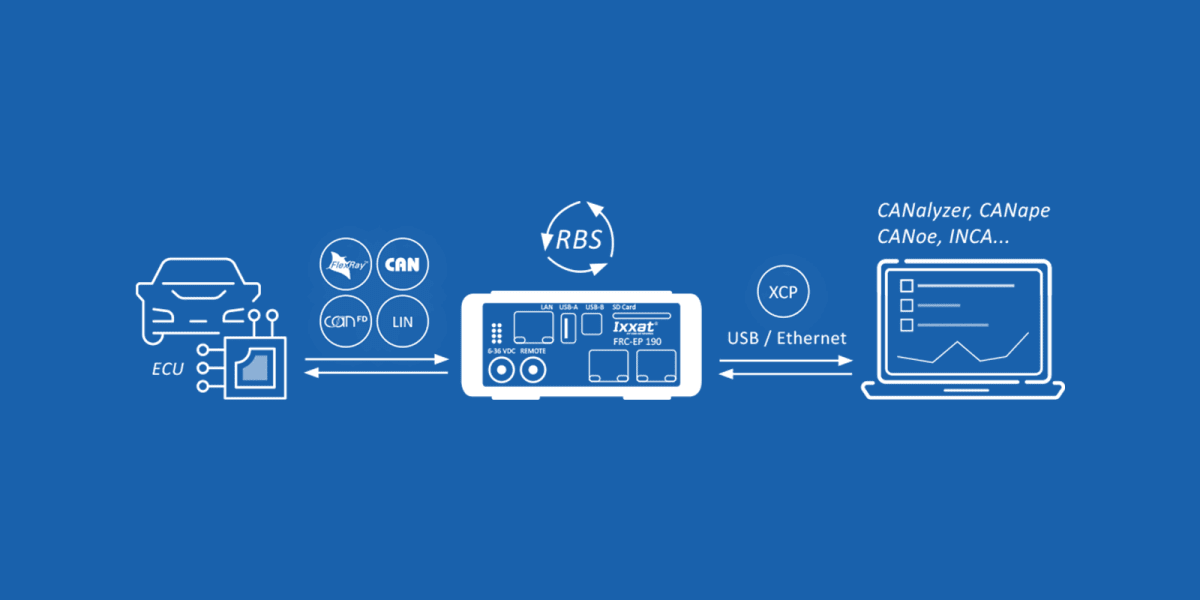
Residual bus simulation is used to simulate ECUs or parts of a vehicle. Elsewhere it has to be coded by hand in a scripting language. At Ixxat it is generated automatically from the vehicle description database defined in the integrated editor: all you do is select the ECUs you want to simulate.
ACT then takes care of detecting which messages must be sent, spotting those that contain CRCs or alive counters, generating the modules that compute them, and cross-compiling and integrating that C code into the rest of the testing configuration. All through wizards, with no programming effort. Nothing stops you from adding your own code or algorithm to the generated modules.
XCPonEthernet — to control or adjust the simulation running on a Mobilizer or FRC-EP, a compatible third-party tool can connect to it. ACT generates an A2L description file listing all the signals being sent when needed. From the third-party tool's perspective, the device becomes a virtual ECU whose signals can be read and written, CRCs and alive counters included.
HIL signal manipulation — on this basis, the signals sent can be manipulated: switching on or off for a defined time or number of cycles, transmission of substitute values, deliberate corruption of CRCs and alive counters. Control goes through the user code, the gateway or XCPonEthernet.
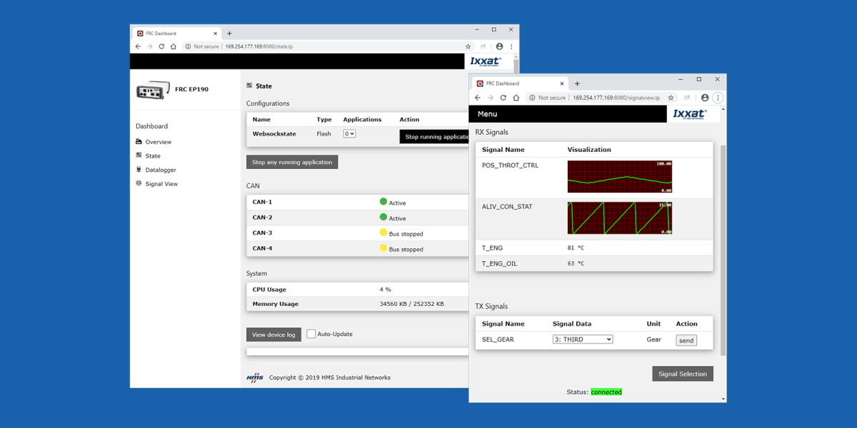
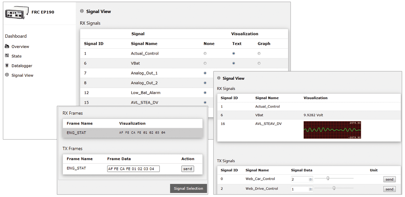
Signal visualization is added to the configuration as a virtual bus. It displays and stimulates all mapped signals through the integrated web server. Any device will do — PC, smartphone, tablet — the only requirement being an HTML5-capable browser. HMS provides a generic page that you can adapt to your own needs. The display device connects via USB, Ethernet or WiFi.
You choose which signals are visualized and whether they appear in textual or graphical form. The visualization configuration is stored either on the device or on the display device, which allows individual views or lets whoever did the configuration control what may be seen. A fully custom HTML5 visualization can also be plugged into the standardized data exchange stream.
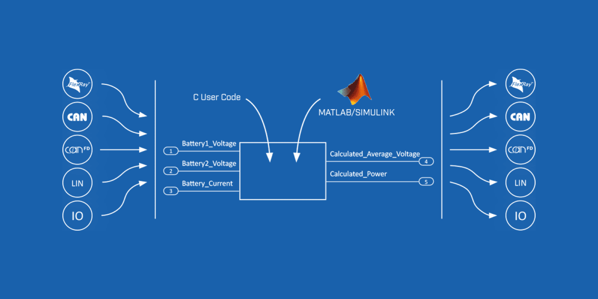
When developing C code is too complex, or when ready-made models already exist, they can be integrated through a dedicated API. Like the user code, a Matlab/Simulink model accesses the mapped signals and messages, which makes it possible to integrate more complex functional models.
If the model already exists, ACT can generate a basic model containing all the required signals and the framework for transforming raw values into physical signal values. All that is left is to design the desired functions, or copy the existing model into the basic model. The executable module is then generated automatically and integrated into the overall configuration.
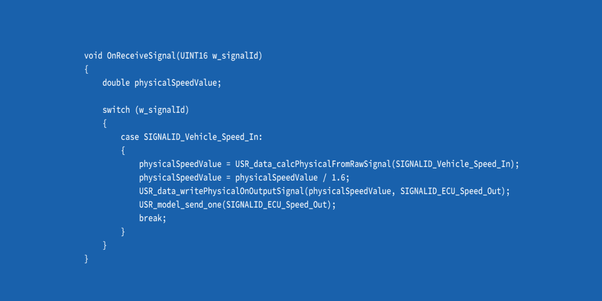
User code — the user code bus is likewise added as a virtual bus. Signals and messages mapped by drag & drop serve as its inputs and outputs. The application is written in standard C: controlling digital outputs or implementing a complex trigger module for the logger becomes straightforward.
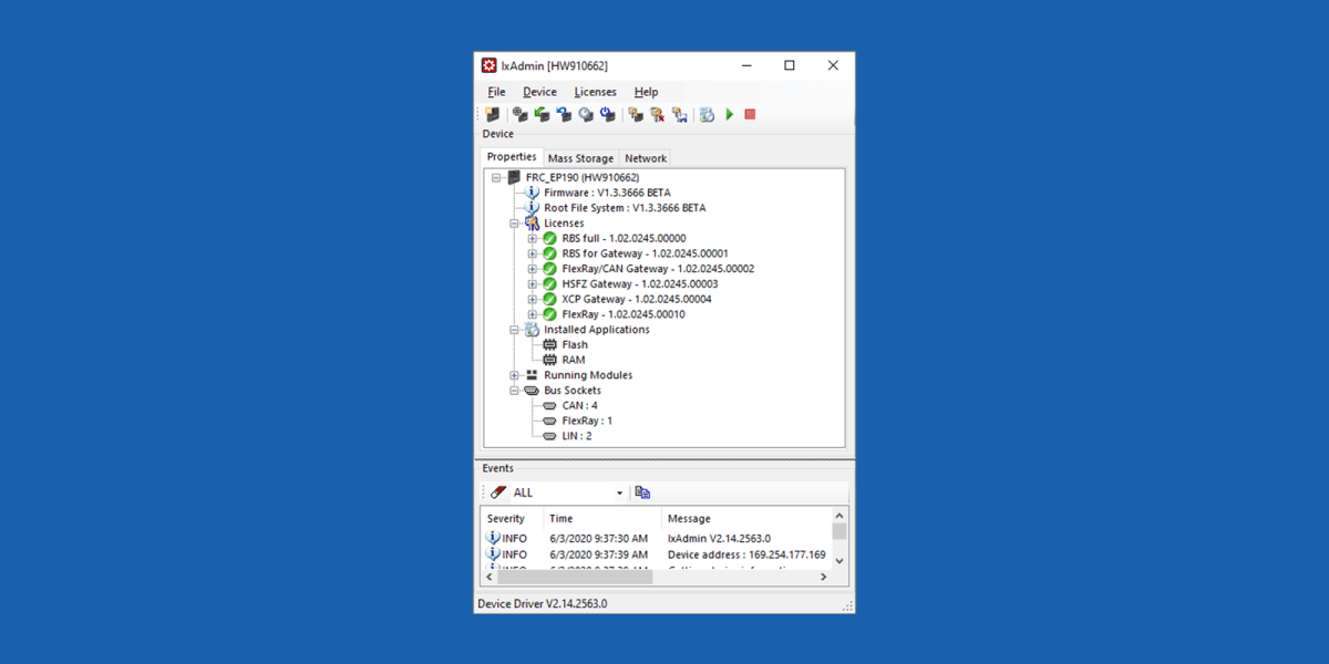
IxAdmin is the PC-based administration tool (freeware) for the FRC-EP, Mobilizer and CANnector platforms, reachable via USB, Ethernet or WiFi: upload and download of configurations, management of multiple configurations, device updates, firmware and board support package, runtime license management, general settings, access to the web-based dashboard and to the logger files. It is also available as a command line tool.
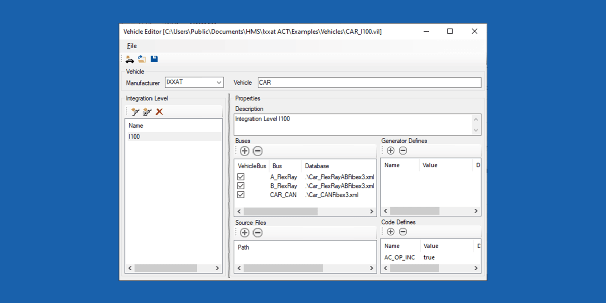
Vehicle Editor — most solutions are based on bus description files (CANdB, DBC, LDF, FIBEX, AUTOSAR-XML). These descriptions hold a great deal of information, but leave out details that are essential to residual bus simulation: CRCs, checksums, alive counter algorithms. The Vehicle Editor lets you build a complete vehicle description database. If things change during the life of the project (a new vehicle integration level), a new variant of that database is easy to create and existing configurations port over without starting from scratch, which saves time and reduces the risk of introducing errors into already verified configurations.
In practice — a LIN to CAN gateway in 6 steps
- Install ACT, available free of charge as the Freeware variant.
- Import your LDF file.
- Select the signals and frames to route to CAN or CAN FD: ACT can generate a new DBC, or you import your DBC/ARXML file and map your signals by drag & drop.
- Add a visualization if needed, also by drag & drop.
- Add your C user code if the signals need to be manipulated.
- Download the configuration to the device. Ready.
Our products
Advanced Configuration Tool


Unsure which variant to pick? Contact us and we will point you in the right direction.